Subject: Crossfire tech - fixing failed attempt to repair broken off screws.
FIXING A FAILED
ATTEMP TO REPAIR BROKEN OFF SCREWS
Initial Release
06/16/08
REVISION 01 – 06/16/08 For Clarity, added ‘F’ designation to
‘fix procedure” steps. Added caution
and changed procedure for drilling out throttle plate holes in Step F7.
REVISION 02 – 06/17/08 Changed photo in Step F7.
REVISION 03 – 07/25/08 Added links to and updated article
references
REVISION 04 – 08/05/08 Add ref to REAMED
bushings article
Difficulty level:
Moderate
Special Machines
required: drill press (or mill) with vice.
© 2008 Steve
Simpson – www.theCUBEstudio.com - steve@thecubestudio.com
IMPOTANT
NOTE:
These tech articles go thru periodic revisions to add or update info. The link
does not change, so check back before you use the instructions to be sure you
are using the latest version.
**
I want to add my thanks for the excellent feedback I have gotten. There’s no
point in doing this if I’m not providing the info people want, so the contributions
from readers are all valuable. **
Note:
use the browser back button after viewing links in this document. Adobe
.PDF versions of these articles (that can be printed including the pictures)
will be available soon
This is a
special addition to the series of tech HOW-TO articles on maintaining and
improving the crossfire injection system. This article is in response to
requests made by readers and it is specific to Crossfire, but the principals
can be applied to any shaft or other part with a failed attempt at screw
extraction.
Articles released so
far:
Crossfire Throttle Body Rebuild including
Installation of standard Shaft bushings Difficulty Level: EASY – Special machines required:
NONE
http://www.thecubestudio.com/CrossfireThrottleBodyRestoration.htm
A special follow-on
article by request is here:
http://www.thecubestudio.com/CrossfireTechFixingFailedAttemptToRepairBrokenOffScrews.htm
Crossfire
Throttle Body Rebuild including Installation and REAMING of accurate Shaft
bushings Difficulty Level –MEDIUM – Special machines required -
Drill press with vice
http://www.thecubestudio.com/CrossfireThrottleBodyRestorationREAMEDBushings.htm
Straightening bent
shafts and arms. Difficulty level: EASY – Special
machines required: bench Vice.
Above operation IF arms are
loose on shafts. Difficulty level: Moderate – Special machines required:
Brazing torch.
http://www.thecubestudio.com/CrossfireThrottleBodyStraigteningBentThrottleShaftArms.htm
Building your own
water manometer for $6 in materials from any hardware store. Difficulty level: EASY – Special machines required:
NONE
http://www.thecubestudio.com/CrossfireHomeBuiltManometer.htm
Correctly and
accurately balancing the Throttle bodies. Difficulty level: EASY – Special machines required:
Water Manometer, air passage plugs (home made)
Above operation IF balance screw if
still welded. Difficulty level: Moderate – Special machines required: Rotary
cut-off tool or hacksaw
http://www.thecubestudio.com/CrossfireThrottleBodyBalancing.htm
Follow on articles will cover:
Adding sealed
stainless ball bearings to the TB shafts instead of simple bushings. (best)
Difficulty level: Advanced – Special machines required – Lathe
Note: After some thought
and discussion, I have concluded that this is NOT a do-it-yourself project and this article may not be released.
Feel free to comment on that.
Rebuilding the
injector POD. Difficulty level: EASY – Special
Machines required: NONE
This will be the next
article released and the article now contains some optional special performance
modifications which will require
machining. Standard rebuild is still EASY no special tools.
Porting the crossfire
manifold. Difficulty level:
Advanced – Special Machines required: Die Grinder (not a Dremel tool), Non-ferrous
carbide cutters, Sawzall or
rotary cut-off tool, Milling
machine. Metal forming skills.
One additional article
specific to the 1982 Collector Edition Rear Glass Hatch is here:
http://www.thecubestudio.com/CollectorEditionHatchHingeInstallationInstructions.htm
FIXING A FAILED
ATTEMP TO REPAIR BROKEN OFF SCREWS
You
need these items available from your own tool box or any hardware store:
A
piece of 1/8” (minimum) thickness by ¾” to 1-1/2” wide steel. This can be a new
piece from the hardware store for a couple bucks or an old door hinge or heavy
shelf bracket . . whatever you have lying around.
Drill
bits
#6-32
specs a NUMBER 36 drill bit (.1065”) but you probably have a 7/64” (.1094”)
which will work fine.
#8-32 specs a NUMBER 29 drill bit (.1360”) but you
probably have a 9/64” (.1406”) which will work fine.
#6-32
and/or #8-32 tap . . do not need
fancy, just plain old hardware store taps (Vermont or Hanson) – couple bucks.
#6-32 and/or #8-32 screws
over ¼” long. – OK now you need fancy - do NOT use slotted screws that you find
hanging in little packs at Lowes/Home depot, etc. Get good button head cap
screws from the specialty nuts and bolts section . . you now the ones in the
little partitioned drawers that they burn you a buck each for. These fasteners
usually are allen head and are high strength. I use torx®
because I despise allen heads, but you probably won’t find torx ®
at the
hardware store, so allen head is the next best thing. And yes, I’ve gone to the
hardware store myself and paid an outrageous $1.15 for a single stainless M4 x
25 screw to use for a Crossfire Idle stop. In a box of 100, they cost me 17
cents . . so no whining, just buy
the screws already.
Speaking
of whining, let’s talk repair psychology. These types of repairs can be very
frustrating and any normal person is going to become less and less patient as
things go from bad to worse. Then the concept of a ‘destroyed’ part floats into
the scene and adds another layer of anxiety. So, to avoid all of that, keep in
mind that it takes a lot to ‘destroy’ a part to the point it cannot ever be
repaired. In the case of throttle shafts, even a loose arm or a very nasty hole
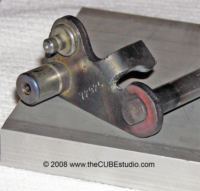
can be brazed up and the shaft re drilled and tapped or even an entire new
shaft can be made up fairly easily. Here is a new custom shaft I made for a
current project. The steel arm is a modified Crossfire piece:
http://www.thecubestudio.com/pictures/Dually/ShaftNewEndPeenedWEB.jpg
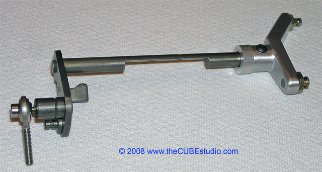
And
the completed shaft.
http://www.thecubestudio.com/pictures/Dually/ShaftNewCompletedWEB.jpg
So
worst case is not that bad. Take your time, follow the steps here and you CAN
fix a very jazzed up shaft.
First
we’ll look at
The correct way to repair a broken off screw and then the way to fix
things up if the repair goes badly, of if you get a jazzed up shaft from a
‘friend’ that needs fixing.
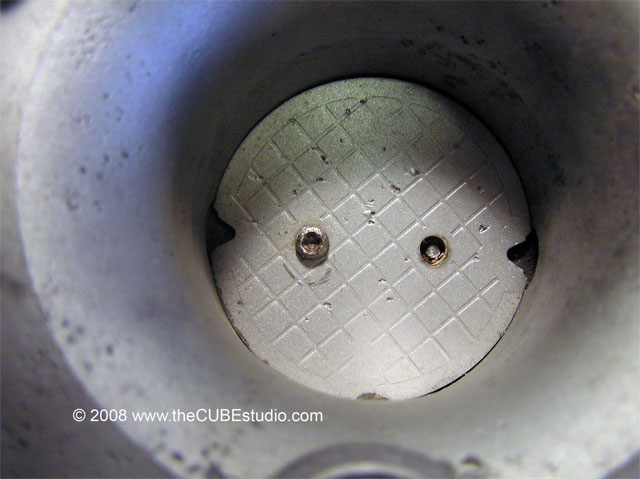
Assess
the damage. Let’s see what we have here:
http://www.thecubestudio.com/pictures/FixTBshaftHoles/LookDownBoreWEB.jpg
OK,
that’s ugly . . let’s fix it up.
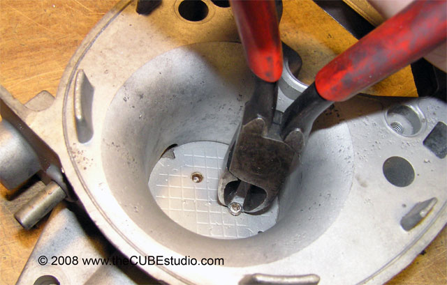
Get
the shaft out. That is covered in another article here:
http://www.thecubestudio.com/CrossfireThrottleBodyRestoration.htm
http://www.thecubestudio.com/pictures/FixTBshaftHoles/TurnScrewWithCuttersWEB.jpg
Center
punch the broken off screw. Unless you have a mill and a spotting drill bit,
you MUST have a good center punch mark for the drill bit to follow. A bit this
tiny will wander all over the place. Trying to drill out an broken off screw
without a center punch mark or ‘choking up’ on the bit (more on that later) is
how most repairs attempts go south.
Tips:
Take
your grinder and make a very slight depression or ‘bowl’ on top of the broken
off screw. Note we always attack from the broken side, not the bottom of the
screw.
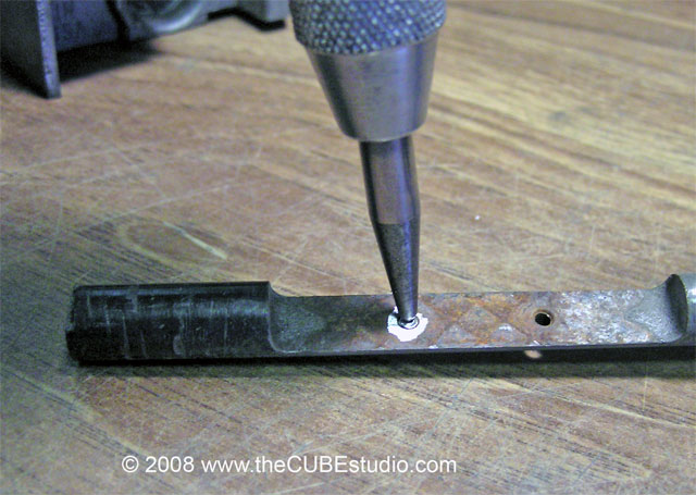
http://www.thecubestudio.com/pictures/FixTBshaftHoles/GrindBrokenScrewInsideWEB.jpg
Now
center punch right in the middle of the screw shaft:
http://www.thecubestudio.com/pictures/FixTBshaftHoles/CenterPunchUsingWEB.jpg
Oops!
Get a little off center? No problemo. Did you know you can actually ‘move’ a
center punch mark? Here’s how; just put the punch in the old mark, angle it as
if the punch can ‘push’ the hole sideways and whack it again. OK, it’s redneck,
but it works:
http://www.thecubestudio.com/pictures/FixTBshaftHoles/CenterPunchMoveWEB.jpg
Don’t
even think about drilling until you have something that looks about like this:
http://www.thecubestudio.com/pictures/FixTBshaftHoles/CenterPunchMarkWEB.jpg
If
your punch mark is hopelessly off center, grind the ‘bowl’ a little deeper and
try again.
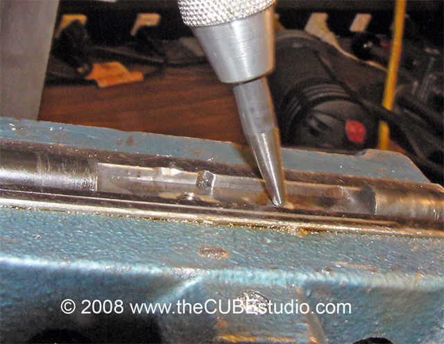
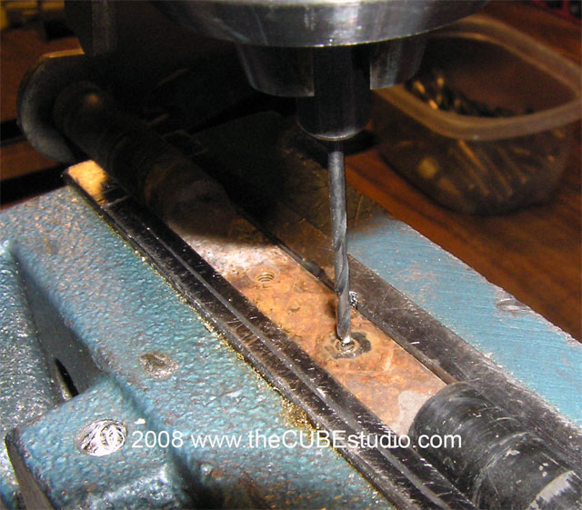
Drill
out the screw.
http://www.thecubestudio.com/pictures/FixTBshaftHoles/DrillFor6WEB.jpg
Tip:
Ever
play baseball? You can ‘choke up’ on a drill bit just like you did on the bat. This
is another trick that stabilizes a tiny drill bit and helps it not wander over
to New Jersey as soon as it touches the work piece. With a collet, this does
not harm the drill bit. With a drill chuck as shown here, you can easily crush
the tiny drill bit into oblivion because you are actually clamping on the
flutes. Be gentle and you can get away with this trick, but even if you destroy
the bit in the process, it’s a $2 bit and you may save your crossfire shaft so
the sacrifice is logical.
http://www.thecubestudio.com/pictures/FixTBshaftHoles/DrillFor6ChokeWEB.jpg
If
you want to go Pete Rose and increase your odds, you can use the ‘choke up’
trick on a 1/16” bit and drill a tiny hole in the middle first. The smaller
drill will follow the center mark better and then the larger drill will then
follow the small hole.
http://www.thecubestudio.com/pictures/FixTBshaftHoles/DrillFirstHoleWEB.jpg
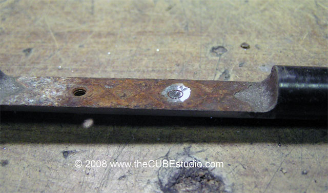
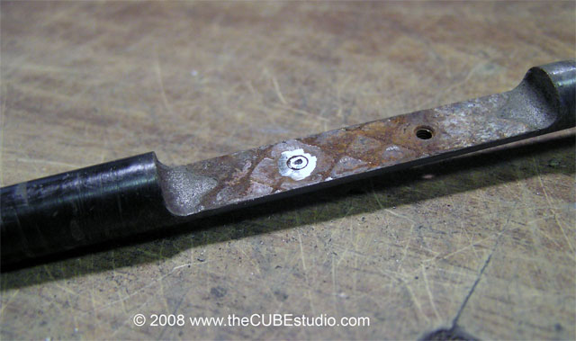
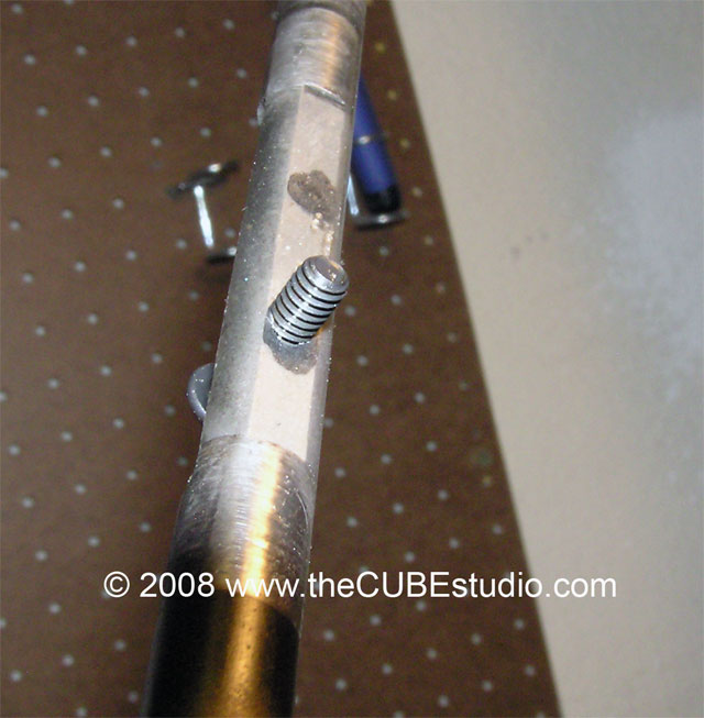
The
shaft is drilled out, so you simply run the #6-32 tap thru and viola, Miller
time:
http://www.thecubestudio.com/pictures/FixTBshaftHoles/New6ScrewInShaftWEB.jpg
Properly,
the hole should be countersunk, which helps the tap and also the screw start
into the hole better. If you choose to do this, keep it absolutely minimal as
we want as many threads as possible in this thin bit of shaft.
FINISH
CLEAN the threaded holes and the fasteners with brake
or carb cleaner before you do final assembly into the TB. Use blue or red or green
Loctite on the screws. I use a drop of green on the protruding end of the screw
after it’s tight. If you haven’t used this stuff before, be aware that the
Green is designed to ‘wick’ into tight places so it is very thin (runny,
watery) A tiny squeeze on the tube can make a huge mess . . and you definitely don’t want it
running down the shaft into the bearings or bushings or whatever you used for
the rebuild.
Next up. How to
fix up a failed repair attempt.
OK, now for the fun part. Let’s say you just left a
quarter on your workbench next to the shaft hoping to lure the screw extractor
fairy. She shows up, but she was
in a hurry and skipped the all important STEP 3 above so in the morning, the
quarter is still on your bench and your throttle shaft now looks something like
this:
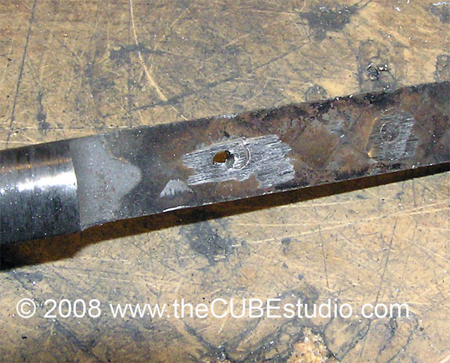
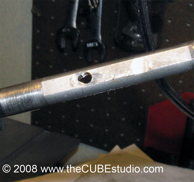
http://www.thecubestudio.com/pictures/FixTBshaftHoles/BadlyDrilledShaftWEB.jpg
I took a perfectly good shaft and jazzed it up nasty
in order to show an example of the worst mess that anyone could possibly make.
So if we can fix this, we can certainly fix your tiny mistake, right? No
problemo.
STEP F1
Locate appropriate material. Do not try to use wood,
aluminum, rock hard pizza crust from last week or anything else except 1/8”
thick steel (minimum). What you
are actually going to build is a redneck drill bushing. Real ones that are used
in manufacturing are made from hardened tool steel. You only need to use yours
once, so you can get away with using soft steel, but even that is not exactly a
guarantee of success. Using anything else is a guarantee of failure.
http://www.thecubestudio.com/pictures/FixTBshaftHoles/BushingMaterialFitUpWEB.jpg
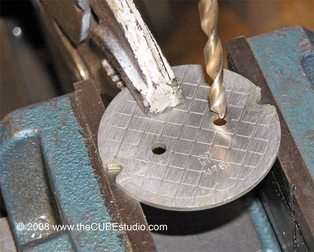
STEP F2
Mark where you need to drill the bushing hole:
http://www.thecubestudio.com/pictures/FixTBshaftHoles/BushingMarkDrillPositionWEB.jpg
Do the deed:
http://www.thecubestudio.com/pictures/FixTBshaftHoles/BushingCreateHoleWEB.jpg
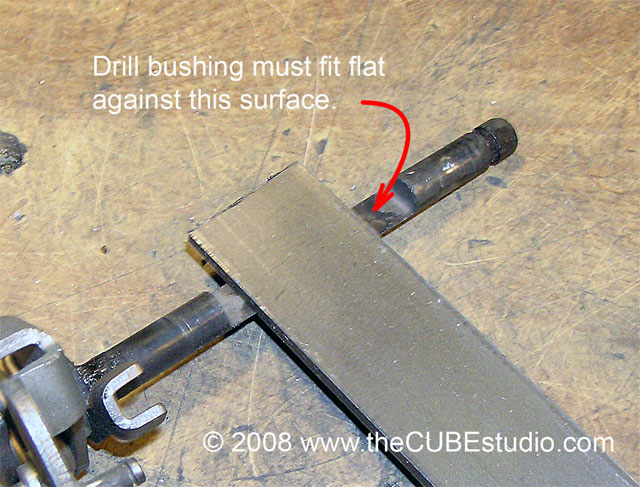
STEP F3
Very important step. If you don’t get this right,
there will be no joy. Line up the drill bushing hole over the original broken
off screw shaft and clamp it securely to the shaft with a locking pliers (Vice
Grip).
http://www.thecubestudio.com/pictures/FixTBshaftHoles/BushingPositionWEB.jpg
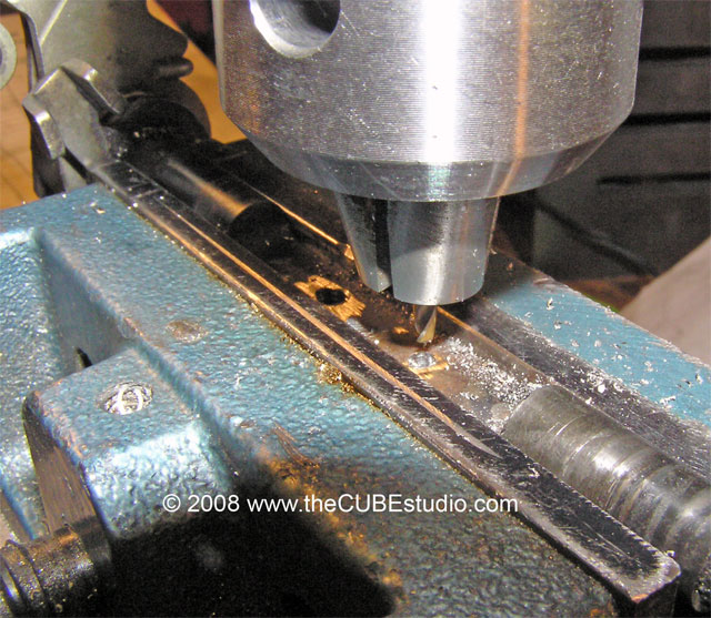
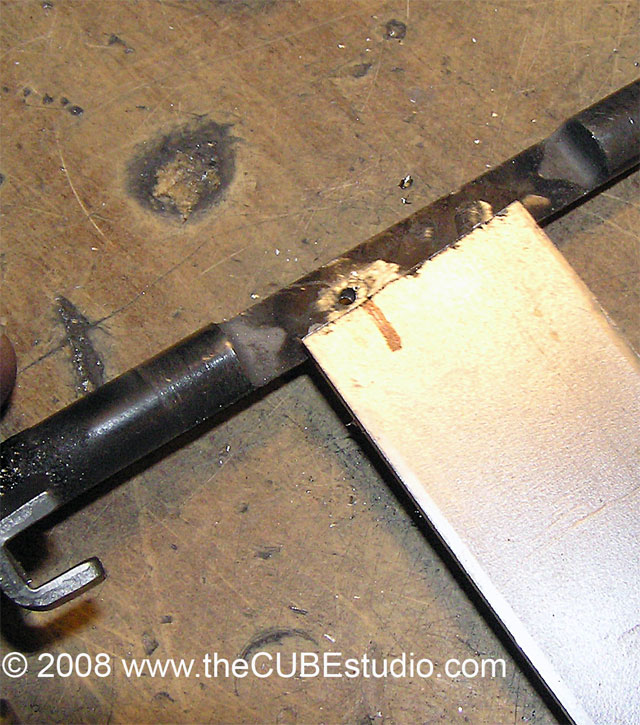
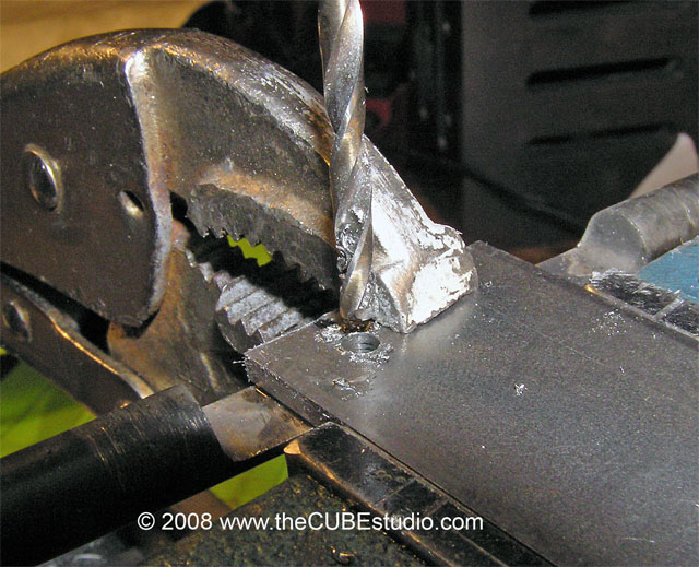
STEP F4
Slap that baby back in the vise and slowly and
carefully using the bushing hole as your guide, drill thru the shaft. This is
why the bushing must be made from steel. If it were aluminum or something
similar, the drill bit, which is sharp on the sides, would jump sideways into
the incorrectly drilled hole in your shaft and simply hog out bushing hole in
the process. The idea here is that the bushing is as hard as the shaft and
screw and it will sacrifice a bit of it’s side, but will hold the bit in place
enough to get a hole in the shaft where you want the hole to be . . which in
this case is right over the broken off screw.
http://www.thecubestudio.com/pictures/FixTBshaftHoles/BushingAndShaftDrillThru8WEB.jpg
If you follow all of the steps exactly, this WILL
work and your new hole will now be ready to tap . . BUT, do not unclamp the
bushing yet. Leave the setup as it is.
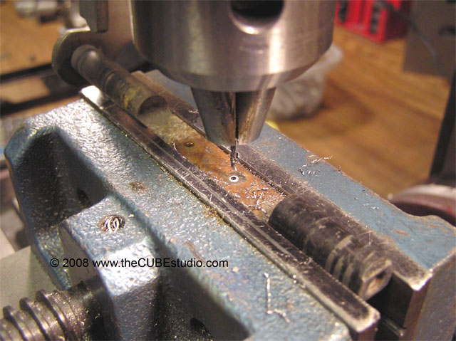
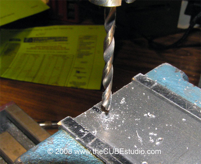
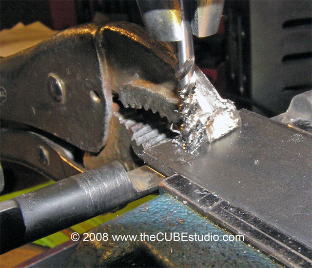
STEP F5
Time for more sacrifice. Tap 8-32 thru the bushing
itself AND the shaft. This will further align the new bolt with the original
position of the old screw.
http://www.thecubestudio.com/pictures/FixTBshaftHoles/TappingThruBushingTopWEB.jpg
BTW, You do not need a fancy spiral tap like this. A
plain old El Cheapo hardware store tap will do fine. I strongly suggest you
drive the tap by hand. Even if you have it chucked up to keep it straight. Turn
the chuck by hand. Use oil . . . preferably tapping fluid . . it makes a big
difference here.
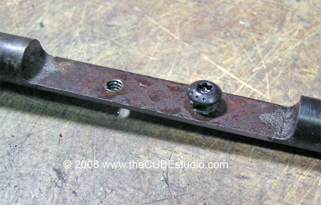
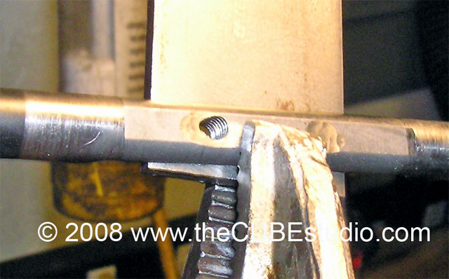
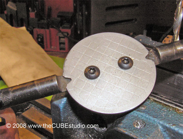
STEP F6
Oh wait, there is no step 6 . . you’re done!
This is what your new tapped hole will look like from
the bottom. Half of those threads are in the bushing.
http://www.thecubestudio.com/pictures/FixTBshaftHoles/TapThruBushBottom01WEB.jpg
Because this was such an extreme example, there
remains a bit of the badly drilled hole, but you can trust me on this; it will
not effect the ability of the new screw to hold the plate on just fine.
http://www.thecubestudio.com/pictures/FixTBshaftHoles/RepairedHoleBottomWEB.jpg
http://www.thecubestudio.com/pictures/FixTBshaftHoles/New8ScrewBottomWEB.jpg
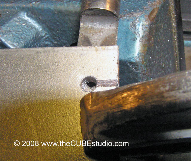
STEP F7
Well, we are done with the shaft, but since we had to
go to a #8 screw, the holes in the throttle plate need some attention: #8 screw
is .164” so 11/64” or 3/16” should ‘git er done’.
Hold the plate with a pliers by the top and bottom
surfaces and just rest it on TOP of the vice jaws to drill it out. That way
there is no chance of nicking up the edges which will effect the operation of
the TB.
http://www.thecubestudio.com/pictures/FixTBshaftHoles/DrillThrottlePlateWEB.jpg
This is what you want to end up with. Looks a little
Robo with the relatively larger screw heads, but it will work fine and will
outlast the rest of the car.
http://www.thecubestudio.com/pictures/FixTBshaftHoles/PlateWithNewScrews8WEB.jpg
FINISH
CLEAN the threaded holes and the fasteners with brake
or carb cleaner before you do final assembly into the TB. Use blue or red or
green Loctite on the screws. I use a drop of green on the protruding end of the
screw after it’s tight. If you haven’t used this stuff before, be aware that
the Green is designed to ‘wick’ into tight places so it is very thin (runny,
watery) A tiny squeeze on the tube can make a huge mess . . and you definitely don’t want it
running down the shaft into the bearings or bushings or whatever you used for
the rebuild.