Subject: Crossfire Throttle Body Balancing
Added tip to Step 2
Added photos and tech article link to Step 3
Added
testing guideline to Step 4
Added links to WinALDL and Factory Shop Manual to
Step 5
Revision 03 – Released 07/25/08
Added links and updated to article desriptions
REVISION
04 –
add ref to REAMED bushing article
Correctly
and accurately balancing the Crossfire Throttle bodies
Difficulty level:
EASY
Special Machines required:
Water Manometer, optional tachometer or
WinALDL.
© 2008 Steve
Simpson – www.theCUBEstudio.com - steve@thecubestudio.com
Note:
use the browser back button after viewing links in this document.
Balancing the throttle
bodies of the crossfire injection system is arguably the most misunderstood
process of maintaining the car. In this tech HOW-TO article I will cover in
detail the theory and process of balancing and synchronizing the crossfire throttle
bodies. Information, specs, and procedures described here are taken directly
from the GM factory vehicle service manuals and specific GM fuel injection
service manuals and bulletins.
Simple home build
manometer and IAC plugs will be used to accurately diagnose the behavior of the
induction system and balance procedures according to the GM service manuals are
incorporated.
This is the third in a series of tech HOW-TO instructions
for maintaining a crossfire injection system.
Articles released so far:
Articles released so
far:
Crossfire Throttle Body Rebuild including
Installation of standard Shaft bushings Difficulty Level: EASY – Special machines required:
NONE
http://www.thecubestudio.com/CrossfireThrottleBodyRestoration.htm
A special follow-on
article by request is here:
http://www.thecubestudio.com/CrossfireTechFixingFailedAttemptToRepairBrokenOffScrews.htm
Crossfire
Throttle Body Rebuild including Installation and REAMING of accurate Shaft
bushings Difficulty Level –MEDIUM – Special machines required - Drill
press with vice
http://www.thecubestudio.com/CrossfireThrottleBodyRestorationREAMEDBushings.htm
Straightening bent
shafts and arms. Difficulty level: EASY – Special
machines required: bench Vice.
Above operation IF arms are
loose on shafts. Difficulty level: Moderate – Special machines required:
Brazing torch.
http://www.thecubestudio.com/CrossfireThrottleBodyStraigteningBentThrottleShaftArms.htm
Building your own
water manometer for $6 in materials from any hardware store. Difficulty level: EASY – Special machines required:
NONE
http://www.thecubestudio.com/CrossfireHomeBuiltManometer.htm
Correctly and
accurately balancing the Throttle bodies. Difficulty level: EASY – Special machines required:
Water Manometer, air passage plugs (home made)
Above operation IF balance screw if
still welded. Difficulty level: Moderate – Special machines required: Rotary
cut-off tool or hacksaw
http://www.thecubestudio.com/CrossfireThrottleBodyBalancing.htm
Follow on articles will cover:
Adding sealed
stainless ball bearings to the TB shafts instead of simple bushings. (best)
Difficulty level: Advanced – Special machines required – Lathe
Note: After some thought
and discussion, I have concluded that this is NOT a do-it-yourself project and this article may not be released.
Feel free to comment on that.
Rebuilding the
injector POD. Difficulty level: EASY – Special
Machines required: NONE
This will be the next
article released and the article now contains some optional special performance
modifications which will require
machining. Standard rebuild is still EASY no special tools.
Porting the crossfire
manifold. Difficulty level:
Advanced – Special Machines required: Die Grinder (not a Dremel tool),
Non-ferrous carbide cutters, Sawzall
or rotary cut-off tool,
Milling machine. Metal forming skills.
One additional article
specific to the 1982 Collector Edition Rear Glass Hatch is here:
http://www.thecubestudio.com/CollectorEditionHatchHingeInstallationInstructions.htm.
Correctly
and accurately balancing the Crossfire Throttle bodies
First,
some background on the common problems with the throttle bodies on Crossfire.
There
has been a lot of confusion in the community about why throttle bodies need to have
bushings installed on the shafts. The standard GM Crossfire throttle bodies are
actually 4 cyl models (the only TBs GM had at the time) and have no bushings or
bearings on the shafts the way many new cars do today. The steel shaft merely
twists back and forth in a drilled hole in the soft zinc alloy die casting. The resulting wear together with
wear in the linkage itself causes the two throttle bodies to be out of
synchronization with each other. It is very important that the two TBs are open
the same amount and that they open together. Worn shafts and linkage cause the
rear throttle body to open ahead of the front causing a very noticeable
stumble. When the throttle is released, the two throttle bodies do not always
come back to the same resting place so the idle can be good one time and then
bad the next and then good again.
This erratic
behavior makes problems very difficult to correctly diagnose by persons not
experience with this system.
Some theory:
Most carburetors or throttle
bodies have two (sometimes 4) throttle plates. Those two plates are on the same
shaft and therefore they always move identically, or in a synchronized
fashion. When the throttle plates
are in separate places and connected by a linkage, the setting of that linkage
and it’s ability to maintain that setting will determine the accuracy of the
synchronization. It is not difficult to understand that the further apart the
throttle plates are, the more effect an unsynchronized condition has on the
induction system.
The terms ‘synchronized’ and
‘balanced’ are in practical terms describing the same thing. From here on we will just use the term
‘balance’.
‘Balance’ relative to
throttle bodies simply means that each is passing the same amount of air. To
accomplish this, we need two things; a way to measure the air flow, and a way
to adjust the throttle bodies. All multi carb systems have some provision for
balancing. On the Crossfire system, each throttle body is equipped with a tiny
square hole in the throat wall,
just above the throttle plate. Air rushing past this hole tries to drag
some air out of the hole. This creates a weak vacuum in the hole that is
proportional to the air flow and can be measured by means of a very sensitive
vacuum measuring device . . a manometer.
A screw is provided on the
crossfire linkage to allow one
throttle body to be adjusted to match the flow of the other . . or to be ‘balanced’. Thru testing, the factory determines at
which flow rate the balancing would be most accurate and prior to doing the
actual balance, you simply adjust the idle speed to attain that flow as
measured by the manometer. Once you have the throttle bodies at that prescribed
flow rate, in this case 6” of water on the manometer, you then simply match the
flow of one TB to the other and then lock that adjustment.
So the process goes simply
like this:
FIRST: Change the idle speed
to the optimum flow rate for balancing. This is done by changing the idle
speed.
SECOND: Do the actual
balancing
THIRD: Restore the idle
speed.
Terminology traps:
The first step above, which
changing the idle speed to get to a good flow rate for balancing is called
‘setting initial air’. It would be more clearly understood if they called it
something like “changing the idle speed to get to the air flow rate where it is
best for balancing”
The second step is sometimes
called synchronizing, balancing, matching, or nothing at all. That is the only
actual ‘balance’ adjustment step where you match the flows.’
So don’t be confused by the
odd terminology. Whatever it is called, you basically are taking the TBs to a
place where they can best be balanced, and then taking them back. That’s all
there is to it.
The factory assumes a new
and unworn system, so it is logical that their procedures stop at balancing the
system at idle. On a new system that has not been ravaged by years of corrosion
and wear and abused by mechanics unfamiliar with the system, a good balance at
idle translates into a good balance at al times. But that may not be the case
after 20+ years of service. Therefore I am going show you how to extend the
procedure to include a the process of determining the overall condition of the
TB shafts and linkage by using actual measurements on the manometer and not by
speculation based on the mileage of the car, some sound it makes, or the
position of the moon.
The computer that runs the
car is called an ECM or ECU (Electronic Control/Command Unit/Module) I highly
recommend you get a laptop computer, a cable to connect it to the car’s
computer and the free software to talk to the car’s computer.
Available here:
http://www.aldlcable.com/sc/details.asp?item=aldlobd1u
This will allow you to see
the RPM on the computer screen as well as the readings from all of the sensors. You should adjust
one sensor, the TPS or Throttle Position Sensor at the end of the balancing
procedure. This is extremely easy to do with the values right on your laptop
screen.
It is possible to use the
car’s dashboard tachometer and a digital voltmeter to do the associated tasks.
If you do not have a
manometer and IAC plugs to use, this article has instructions to make them:
http://www.thecubestudio.com/CrossfireHomeBuiltManometer.htm
CAUTION: this procedure involves having the transmission in
drive with the engine running. C3 corvettes specifically have notoriously lame
parking brakes, so I HIGHLY recommend you have a helper on the brakes at all
times the car is in drive.
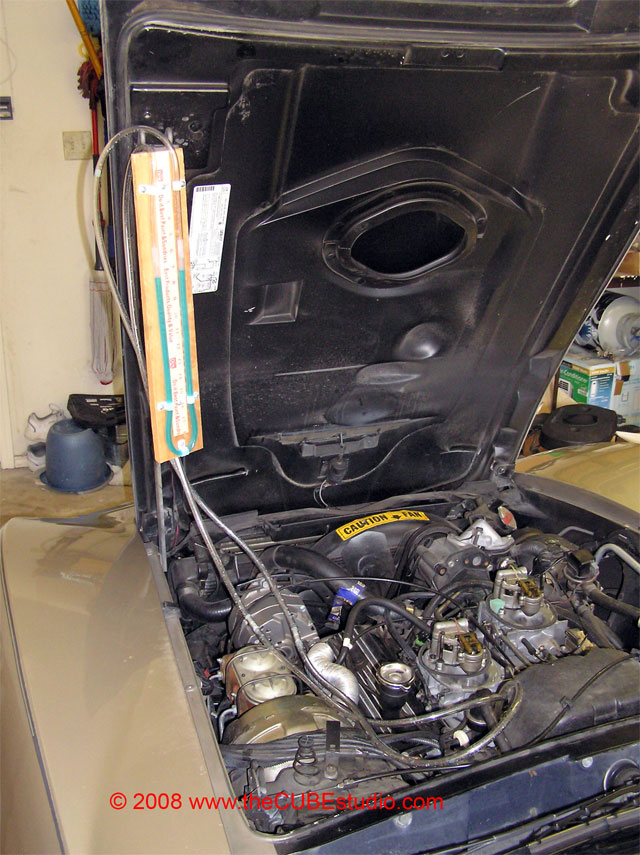
Get the air cleaner off.
There should be a vac line from the Air Cleaner to the TB. Remove that and plug
the port on the TB.
http://www.thecubestudio.com/pictures/CF_TBbalance/ACthermacWEB.jpg
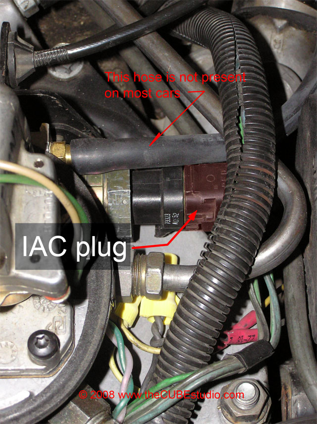
Unplug the IAC motor on each
Throttle body. They are in the same position on each, and the location of the
IAC on the FRONT TB is shown here slightly shaded red for clarity.
http://www.thecubestudio.com/pictures/CF_TBbalance/IACplugLocationWEB.jpg
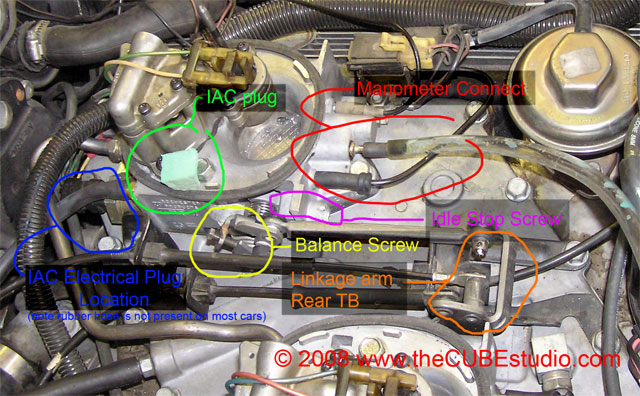
Now, using the IAC plugs you
made earlier, plug the IAC holes, shown here color coded Green:
http://www.thecubestudio.com/pictures/CF_TBbalance/TBMapWEB.jpg
WHY?
You are about to
manually change the idle speed of the engine to get that ‘best flow rate’ or
‘initial air’ that we talked about earlier. The ECM has the job of maintaining
the idle speed and it will try to correct the idle speed using the IAC (Idle
Air Controllers) as soon as you begin to adjust it. So we disable it’s ability
to interfere and we plug the ports to guarantee we have equal flow i.e.
none, to each TB.
Not really so
mysterious when you break it down.
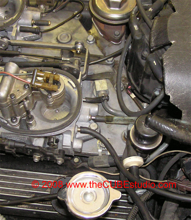
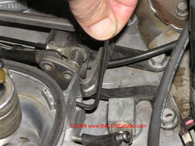
Find
the Idle stop screw on the REAR TB as shown in the photo. If there is an anti
tamper cap covering it, you will have to remove the cap in order to use the
idle stop screw.
The
procedure for removing the anti-tamper caps is the same for the front and rear
TB.
Instructions
for removing the Anti-Tamper caps are contained in this Article:
http://www.thecubestudio.com/CrossfireThrottleBodyRestoration.htm
Tip: The factory used
two types of throttle stop screws, a Torx head and a Philips head. The Philips
head is nearly impossible to turn, so if you have one of those, you can go to
any good hardware store and buy an M4x25 (metric) socket head cap screw as a
replacement.
The
Torx head is easy to turn, and Torx keys are available, but not that easy to
find locally, so you might consider replacing the Torx screw also.
There
are two screws on the front TB to check now.
Find
the idle stop screw as shown in the following picture, color coded Violet:
http://www.thecubestudio.com/pictures/CF_TBbalance/TBMapWEB.jpg
It
should NOT be touching the linkage are on the FRONT TB. If it is, you will need
to remove the ant tamper cap and back off or remove the stop screw. If the head
or the rear stop screw is jazzed up, the front screw can be used as a
replacement. No idle stop screw is needed in the front TB.
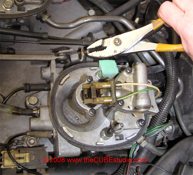
Find
the balance screw as shown in the photo above color coded Yellow.
The
factory welded this adjustment screw after the initial balance to prevent
tampering. The screw head is only about ¼” across, but it may or may not have a
larger ½” collar over it. Either
way, the weld must be cut off if it is present.
Cover
the throttle bodies with wet rags and using a rotary cut off tool of a plain
hacksaw, remove weld material until the screw is free to turn. Be careful
because you cannot get a new screw. It
is an oddball that you will not find anywhere. If you destroy the screw,
it’s not the end of the world, you just have to re-tap the hole for a
conventional size.
STEP
THREE
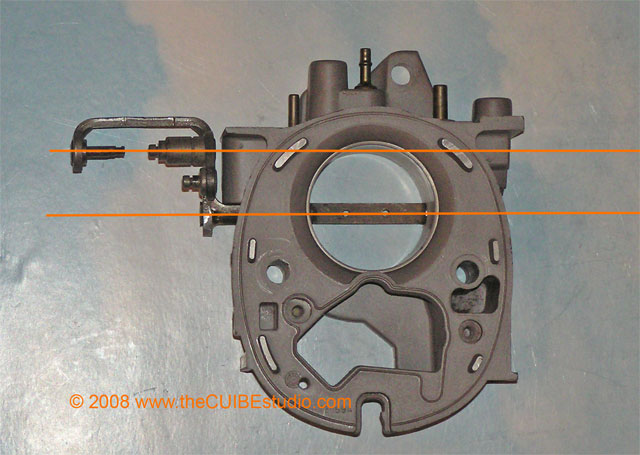
Check
the condition of the linkage arm on the rear TB, shown in the above photo color coded Orange. Occasionally I have
found crossfire systems with the balance screw still welded that had been
balanced sometime in the past by literally bending the rear linkage arm. I have
even seen it written that this is the correct procedure! The crossfire will NOT
work well if the rear arm is bent up, so if it is bent is must be straightened
before you can expect to balance the TBs PROPERLY.
WHY?
Even though the Rear TB shaft arm is a bizarre looking thing, it
still ultimately must exactly match the geometry of the front arm so that the
two throttle plates track together. Think of the link on the main drive wheels
of an old steam locomotive. The wheels are always in perfect sync. They turn
smoothly together degree by degree . Imagine if the distance from the center of
one wheel to the attachment point was different from the other wheel. That is
what happens if the rear TB arm is bent.
Another way to say it is that if the rear arm is bent, you can
imagine that the rear TB could open al the way while the front only opens 80%,
or vice versa. Our objective to do a FULL balance at ALL throttle positions,
the bent arm is not going to allow that to happen.
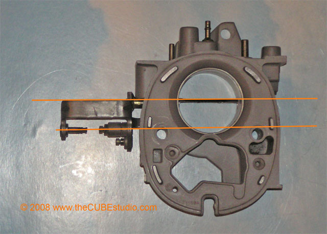
Now
look at is as directly from above as possible with the throttle closed and open
and compare that to the photo.
http://www.thecubestudio.com/pictures/CF_TBrefurb/TopViewOpenWEB.jpg
http://www.thecubestudio.com/pictures/CF_TBrefurb/TopViewWEB.jpg
If
the arm is only very slightly bent, you may be able to straighten it in place.
If it is badly bent, you should remove the TBs and follow the instructions in
the rebuild TB and straighten shafts tech HOW-TO articles.
http://www.thecubestudio.com/CrossfireThrottleBodyStraigteningBentThrottleShaftArms.htm
STEP
FOUR
NOTE: On a manometer the measurement is the TOTAL difference
in the levels, so 6” means 3” on the left and 3” in the opposite direction on
the right.
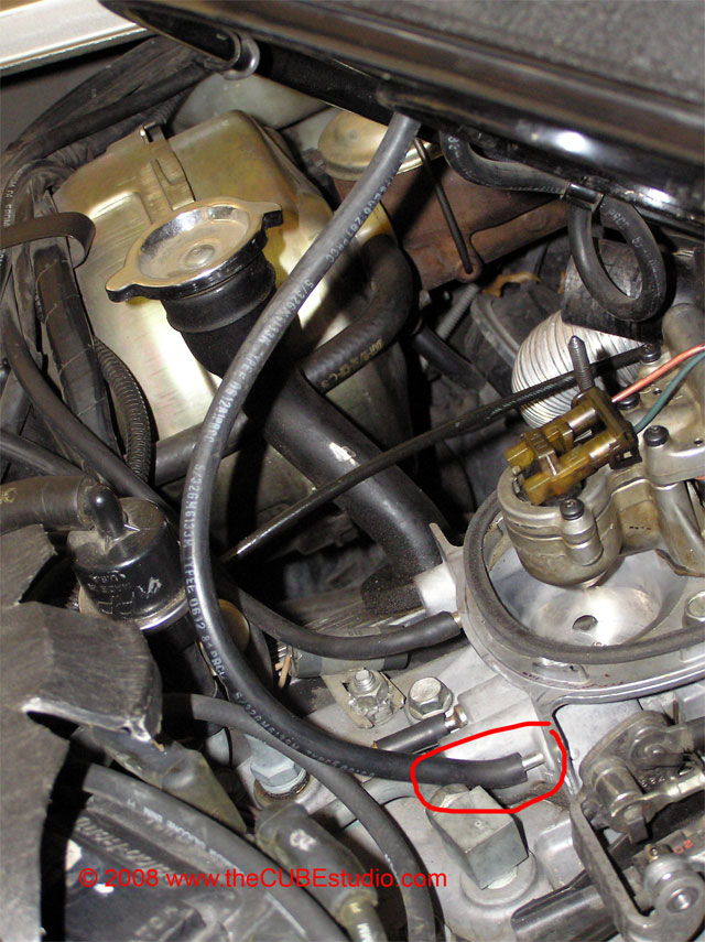
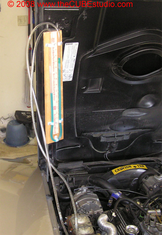
Hang the water manometer
somewhere convenient and connect one leg of the manometer to the CENTER port of
the REAR TB
http://www.thecubestudio.com/pictures/CF_TBbalance/BalancePortLocationWEB.jpg
Put the car in drive and
adjust the idle speed using the REAR TB idle stop screw to attain the
prescribed ‘initial air’ of 6” on the water manometer.
http://www.thecubestudio.com/pictures/CF_TBbalance/Monometer6inchWEB.jpg
WHY?
All we have done
with this step is get the TB to the optimum place for balancing, as determined
by the GM engineers. No more, no
less.
Disconnect the manometer
from the REAR TB and recap the port. Connect the manometer (either leg) to the
FRONT TB center port, as shown in this photo color coded Red:
http://www.thecubestudio.com/pictures/CF_TBbalance/TBMapWEB.jpg
The reading will probably
not be 6”. Using the balance adjustment screw on the front TB linkage, (shown
in the above photo color coded Yellow), NOT the front TB idle stop screw, bring
the front TB to 6” on the manometer.
http://www.thecubestudio.com/pictures/CF_TBbalance/BalanceScrewTurnWEB.jpg
This is a very satisfying
part of the process because typically, your engine will go from stumbling and
bumping and will smooth right out as the front TB approaches 6”. Once you have the
front TB at 6” place a drop of GREEN loctite on the adjustment screw threads to
prevent it turning and ruining your hard work.
At this point, the factory
procedure is done except for resetting the idle speed, BUT we are gong to take
things a step further.
Take the car out of gear
and attach the manometer to both TBs
The manometer should show balance, meaning the water level should be the
same on both sides, or pretty close. If it is not, then readjust the balance
screw to attain a perfect balance. This if more accurate than individually
measuring each TB and that will become very clear in the next steps.
http://www.thecubestudio.com/pictures/CF_TBbalance/ManometerBalancedWEB.jpg
Grab the front TB shaft arm
and without pulling it forward, apply pressure as thought you were trying to
move it up and down. Feel for play in the shaft and observe the manometer. Now
do the same, but front to back.
Now do the same with the
rear TB. Except grab the shaft or arm close to the TB, Feel for play in the
shaft and observe the manometer. Do the same front to back. Now do all of that
again, but holding the arm as far from the TB as possible, out where the link
connects to the front TB.
What we are looking for is
changes in RPM or deviations in the manometer reading.
I've been trying to find a
factory spec on acceptable fluctuation, but there does not seem to be one. It
an interesting problem in that ‘normal’ is going to be different with each mod
the owner does. A ported manifold behaves differently than a stock one for
example. So the following is a guideline based upon my experience:
First and perhaps most important is that you are never going to see
perfection, there will be SOME variation. I have achieved a 1/4" variation
for ALL tests on the bench with special custom fitted throttle plates, but you
probably will not see that on your engine. What you don't want to see is
extreme fluctuations . . like 3 of
4 inches when you put pressure on the shaft arms. That's an indication that you
do not have enough precision in the setup.
Moving the throttle off idle very very slowly is likely to produce some interesting
swings on the manometer. That is not necessarily an indication of problem that
will translate into anything noticeable on the street. Since this behavior is
different on a bench test using only the lid, I suspect it may have something to do with the huge EGR
restriction biasing the TB's at certain flow levels, but I would need to do
bench testing with a stock and then a ported manifold to be sure about that.
To get a real-world simulation of how you can expect your setup to
perform, you need to be observing the behavior of the TBs while moving the
linkage from the same spot as the throttle cable moves it, i.e. the stud on the
rear TB. Move the throttle at about the same speed as you think you will use in
normal everyday driving and the manometer should not move more than about an
inch per side (2" total). Wild swings like 6" to 9" are going to
translate into the dreaded off-idle 'crossfire stumble".
It is possible to have all of the water instantly sucked out of the
manometer when you move the throttle if your setup is really badly worn or you
have misaligned throttle plates, etc. What you are observing with the manometer
swings are one TB opening before the other . . The goal is to have both TBs
open together and to START moving at the same moment. To that end, the front
TB's idle stop screw should NOT be used. If the screw is present , make sure it
is not touching the arm. The front TB's linkage must rest on the rear TB so
that all of the slack in the linkage is taken up. If the front TB shaft is
resting on an idle stop screw then there will be slack in the linkage and the
front shaft will not start to turn until all of that slack is taken up by the
rotation of the rear TB arm. The net result is that the rear TB is opening and
the front is not, which throws the system wildly out of balance and causes the
stumble.
Something else to watch for is that the manometer balance should come
back to the same position each time you release the throttle. If you get a
different (say more than 1/2" total) balance each time the setup returns
to idle, you probably have too much clearance in the shaft bushings.
The above tests should be done with the initial balancing completed and
the engine set back to it's normal idle speed (but obviously not in gear). The
initial balance is done from 6" and it is pretty hard for the setup to
stay steady starting from that low a number as it is extremely sensitive in
that range.
If everything looks good,
move on to step five. If not, it’s time to yank the TBs for give them some
attention.
Using the REAR TB idle stop
screw, set the idle to 475RPM in drive.
http://www.thecubestudio.com/pictures/CF_TBbalance/IdleStopTurnWEB.jpg
Shut off the engine and
unplug the IAC passages and reconnect the IAC motors.
Set the TPS voltage top
.525V using a digital volt meter or WinALDL
The procedure for setting
the TPS manually is in the shop manual on page 6E-60. If you do not have a shop
manual, you really need to get one. Manuals from Chilton’s and Hayes are fairly
worthless and having the GM shop manual offers protection from bad advice.
Available from the source here: www.helm.com
There is no excuse for not
using WinALDL. It is free software
that will run fine on even the slowest desktop or laptop computer. Just get it.
You can make a cable for a
few bucks
http://winaldl.joby.se/aldlcable.htm
or buy a ready made cable
here:
TIP: this is a good time to set the timing. Unplug the
tan/black stripe connector (’82 vette) to disable advance and set timing to 6
degrees. Reconnect the advance wire.
Put the air cleaner back on
and take the car for a test drive above 35 miles per hour to reset the IACs.
TIP: If it is 20 below zero outside, and you have cruise
control, you can disconnect the cable running from the cruise box to the dash
and spin it to trick the ECM into thinking the car is going fast down the road.
When you return from your
drive, your Crossfire should be purring. During your drive you should have
gotten excellent throttle response and no off-idle stumble. If you still have a
drivability problem, you know it is not with the TBs. You actually observed the
behavior of your TBs, so you are no longer operating on guesswork or
speculation, and you will not be chasing your tail by trouble shooting other
systems.
Congratulation, you have
successfully and correctly balanced your crossfire throttle bodies.