Subject: Crossfire Throttle Body Restoration
Revision 02 - 05/18/08 - Added section on fixing broken off
screws. Added alternate tool source. Added notes and clarifications based on
feedback.
Revision 03 - 06/16/08 - Changed tool spec for uniformity.
Added screw size.
Revision 04 - 06/16/08 – Added links to other tech articles
Revision 05 – 07/25/08 – Added links to and
updated article descriptions
Revision 06 – 08/05/08 – Add ref to REMED
bushing article
Crossfire
Throttle Body Rebuild including Installation of Shaft bushings
Difficulty level:
EASY
Special Machines
required: NONE
© 2008 Steve
Simpson – www.theCUBEstudio.com - steve@thecubestudio.com
IMPOTANT NOTE:
These tech articles go thru periodic revisions to add or update info. The link
does not change, so check back before you use the instructions to be sure you
are using the latest version.
NOTE: If you have
access to a drill press, you may consider installing undersized bushings and
then reaming them to obtain correct clearance and alignment. Those instructions
are now released.
Note:
use your browser back button after viewing photo links in this
document. Complete printable Adobe .PDF format versions of these articles
will be available soon.
$65? $70? More? Plus
shipping two ways and weeks of down time?
Rebuilding you own TB bases including adding new
shaft bushings is an easy Do-It-Yourself
project. The special tools and bushings cost only about $30 and it takes
about an hour to do. In the end, you save money, time and you have some nice
tools to use on other projects . . . like doing the TBs of a friend or other
club members.
This is the first in a
series of tech HOW-TO instructions for maintaining a crossfire injection
system.
Articles released so
far:
Crossfire Throttle Body Rebuild including
Installation of standard Shaft bushings Difficulty Level: EASY – Special machines required:
NONE
http://www.thecubestudio.com/CrossfireThrottleBodyRestoration.htm
A special follow-on
article by request is here:
http://www.thecubestudio.com/CrossfireTechFixingFailedAttemptToRepairBrokenOffScrews.htm
Crossfire Throttle
Body Rebuild including Installation and REAMING of accurate Shaft bushings Difficulty Level –MEDIUM – Special
machines required - Drill press with vice
http://www.thecubestudio.com/CrossfireThrottleBodyRestorationREAMEDBushings.htm
Straightening bent
shafts and arms. Difficulty level: EASY – Special
machines required: bench Vice.
Above operation IF arms are
loose on shafts. Difficulty level: Moderate – Special machines required:
Brazing torch.
http://www.thecubestudio.com/CrossfireThrottleBodyStraigteningBentThrottleShaftArms.htm
Building your own
water manometer for $6 in materials from any hardware store. Difficulty level: EASY – Special machines required:
NONE
http://www.thecubestudio.com/CrossfireHomeBuiltManometer.htm
Correctly and
accurately balancing the Throttle bodies. Difficulty level: EASY – Special machines required:
Water Manometer, air passage plugs (home made)
Above operation IF balance screw if
still welded. Difficulty level: Moderate – Special machines required: Rotary
cut-off tool or hacksaw
http://www.thecubestudio.com/CrossfireThrottleBodyBalancing.htm
Follow on articles will cover:
Adding sealed
stainless ball bearings to the TB shafts instead of simple bushings. (best)
Difficulty level: Advanced – Special machines required – Lathe
Note: After some thought
and discussion, I have concluded that this is NOT a do-it-yourself project and this article may not be released.
Feel free to comment on that.
Rebuilding the
injector POD. Difficulty level: EASY – Special
Machines required: NONE
This will be the next
article released and the article now contains some optional special performance
modifications which will require
machining. Standard rebuild is still EASY no special tools.
Porting the crossfire
manifold. Difficulty level:
Advanced – Special Machines required: Die Grinder (not a Dremel tool),
Non-ferrous carbide cutters, Sawzall
or rotary cut-off tool, Milling
machine. Metal forming skills.
One additional article
specific to the 1982 Collector Edition Rear Glass Hatch is here:
http://www.thecubestudio.com/CollectorEditionHatchHingeInstallationInstructions.htm..
Crossfire
Throttle Body Rebuild including Installation of Shaft bushings
First,
some background on the common problems with the throttle bodies on Crossfire.
There
has been a lot of confusion in the community about why throttle bodies need to
have bushings installed on the shafts. The standard GM Crossfire throttle
bodies are actually 4 cyl models (the only TBs GM had at the time) and have no
bushings or bearings on the shafts the way many new cars do today. The steel
shaft merely twists back and forth in a drilled hole in the soft zinc alloy die casting. The resulting
wear together with wear in the linkage itself causes the two throttle bodies to
be out of synchronization with each other. It is very important that the two
TBs are open the same amount and that they open together. Worn shafts and
linkage cause the rear throttle body to open ahead of the front causing a very
noticeable stumble. When the throttle is released, the two throttle bodies do
not always come back to the same resting place so the idle can be good one time
and then bad the next and then good again. This erratic behavior makes problems very difficult to
correctly diagnose by persons not experience with this system.
TIP: It is wise to do the throttle body balancing with a water
manometer (covered in separate documents) before you decide you need to add
bushings. Once balanced, the water manometer will tell you the condition of
your TB bases and you may be surprised to discover that they are fine and only
the linkage wear, which you will have adjusted for, was the culprit.
This
instruction assumes you have the throttle bodies removed from the car. Every
Crossfire owner should have a factory service manual. They are available form
Corvette parts retailers and also from the OEM publisher www.HELM.com
To work on the throttle
bodies, you will need a couple of Torx® screwdrivers. These are common today and available at any parts store
or hardware store. Torx®
sizes are
designated by a number which has no direct relation to any measurement on the
bit . . as do nut drivers or wrenches for example. You will need Torx® T10, T15, and T20. Try to buy a brand name tool. El
Cheapo Torx® tools will simply twist or
wring off . . sometimes damaging
the screw in the process.
Typically a carb shop will
charge about $65, maybe $70 to put bushings in a pair of throttle bodies plus
another $20 to $30 for shipping
both ways and the waiting time.
You can do it for $30 in parts and tools and it takes only about an
hour. And at the end you still have some nice tools that come in handy for
other jobs. Feel free to find an alternate source for these items, I am
including a well know source for your reference and convenience. You can also
buy your Torx® screwdrivers here and save
on shipping.
You
need these part numbers available from :
08840324
- 1/2 “ counter bore
‘aircraft’ type with ¼” shank and interchangeable pilot
08902249
– 3/8 ” pilot for above
06453435
- Bushings 3/8” ID x ½” OD x 3/8”
long
Alternate
source:
3102A19
– 1/2 “ counter bore ‘aircraft’ type with ¼” shank and
interchangeable pilot
3103A22
- 3/8” pilot for above
7095K43
– Bushings 3/8” ID x ½” OD x 3/8” long
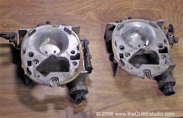
We
begin here with the TB bases on the bench. Pods have been removed. It is not
necessary to take the pods apart to remove them from the TB bases. Just remove
the fuel fittings and then the three screws holding the pod to the base. The
pod comes of easily in one piece.
http://www.thecubestudio.com/pictures/CF_TBrefurb/BeginWithTwoTBWEB.jpg
Remove
the TPS (Throttle Position Sensor) form the side of the Rear TB
http://www.thecubestudio.com/pictures/CF_TBrefurb/RemoveTPSWEB.jpg
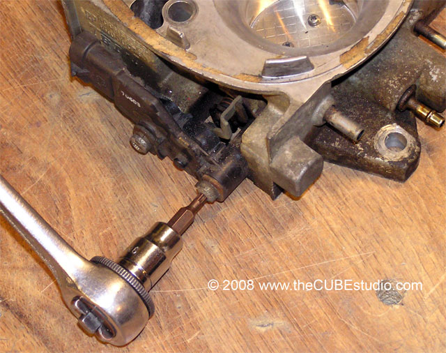
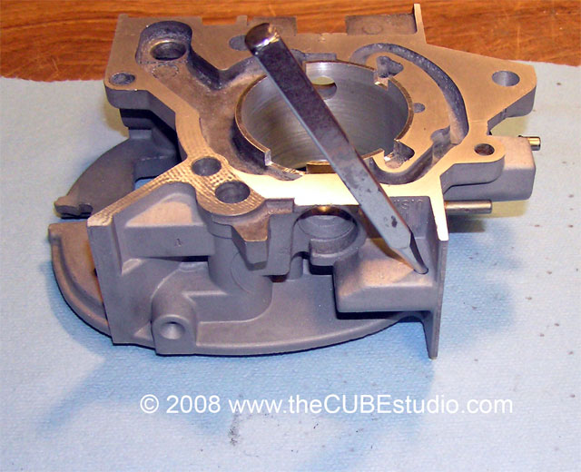
Remove the Torx® head screw holding the actuator arm on the end on
the shaft. This guy is often really tight.
http://www.thecubestudio.com/pictures/CF_TBrefurb/RemoveTPSleverRetainingScrewWEB.jpg
http://www.thecubestudio.com/pictures/CF_TBrefurb/RemovedTPSleverRetainingScrewWEB.jpg
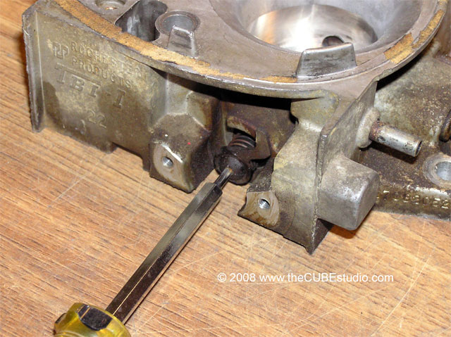
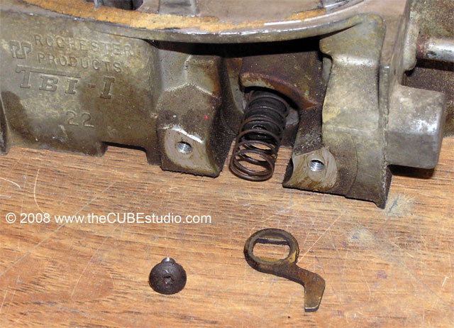
On
the front TB there is a plain old spring in this position that is retained
simply by a few smaller turns at the end of the spring that grab a groove in
the shaft. You need to sort of ‘unwind’ those out of the groove (tiny screw
drivers and an awl work well) and the spring is then free.
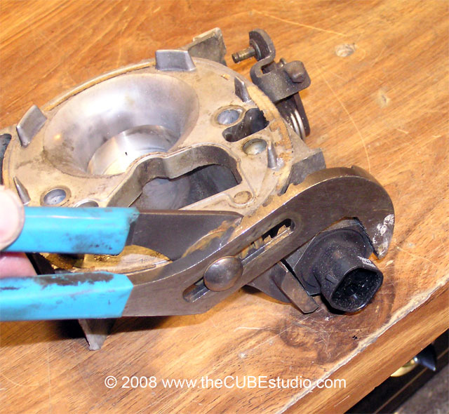
Get the IAC motors off. They
are treaded and not usually very tight. If you do not have wrenches sized for
working on battleships, just use an adjustable pliers like this:
http://www.thecubestudio.com/pictures/CF_TBrefurb/RemoveIACWEB.jpg
The
throttle plates are held to the shaft with small screws that have the ends
peened over by the factory as a safety measure. That needs to be ground or
filed off before the screws will come out. You may hear of a technique where
the screw is simply TIGHTENED until the head breaks off and then you can remove
the threaded part from the bottom. This works on some carbs some of the time.
Try it at your own risk . . and have new M2.5 screws ready.
Carefully
grind off the ends as shown:
http://www.thecubestudio.com/pictures/CF_TBrefurb/GrindOffPeenWEB.jpg
Just
flush with the shaft is plenty:
http://www.thecubestudio.com/pictures/CF_TBrefurb/GroundOffPeenWEB.jpg
You
can also fully open the throttle shaft and carefully file off the end, but it
is easier and faster with a Dremel or larger tool.
Mark the throttle plates
with a sharpie as to orientation. For example ‘this face down, front TB’, and
an arrow toward the vacuum ports. You will want to get the plate back in the
same position.
Once
the peened ends are removed, the screws will come out:
http://www.thecubestudio.com/pictures/CF_TBrefurb/RemovePlateScrewsWEB.jpg
http://www.thecubestudio.com/CrossfireTechFixingFailedAttemptToRepairBrokenOffScrews.htm
The plate is easy to get out
if you open the throttle and pull the plate out the bottom.
With the throttle plates
off, the shafts will pull completely out of the TB. Keep the return springs with
the TB they came form. They are different.
OPTIONAL
STEP
You
can reuse the throttle plate screws, use new screws of the same size (M2.5), or
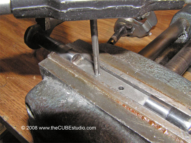
re-tap for larger screws. You can run a 6-32 tap right into the existing holes
and make new larger threads. Try to keep the tap straight and note that the
metal is very soft, so again use an easy touch:
http://www.thecubestudio.com/pictures/CF_TBrefurb/ShaftReTapWEB.jpg
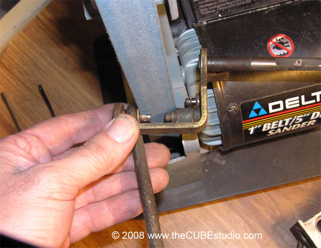
While not necessary to
simply do bushings, you may remove the crimped-on retainer that holds the link
rod to the rear TB linkage arm. Sometimes an inexperienced mechanic has bent up
the linkage arms as a method of balancing the TBs. If that has been done to
yours, it is a lot easier to straighten the arm with the link off. Crossfire will NOT work well if the
arms are bent. It may look
intimidating, but all it takes is some careful grinding, I like to use a little
belt sander like this:
http://www.thecubestudio.com/pictures/CF_TBrefurb/GrindSideCrimpWEB.jpg
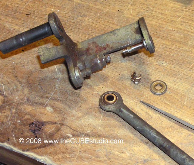
Try to only grind the crimp
and not the stud. Once you have one side of the crimp ground away, it will have
lost it’s death grip on the stud and you can rotate it around 180 degrees with
a pliers and then grind the other side. Eventually it gives up. You may need a
jeweler’s file to remove some deformation on the stud before the link will come
off. Here is what you end up with:
http://www.thecubestudio.com/pictures/CF_TBrefurb/LinkageDisassembledWEB.jpg
Remember that this step is
optional for doing a simple bushing job. If you want to do ball bearings, then
the shafts need some attention that cannot be done with the link hanging on
there. Ball bearing installation is covered in separate instructions. All you
need to replace the crimp is a 3/16” set screw collar available at any good
hardware store in their nuts and bolts section.
Now is a good time to soak
the TB base in carb cleaner and the shafts in rust remover. If you have access
to a blaster or decide to take the castings out to a commercial blaster, make
SURE there is a cap on the balance port connector (the middle vac port) and
that there is strong tape covering the balance port in the throat just above
the throttle plate. There is a chamber in there that often has some varnish in
it and it will collect blast media and make a dandy plug that can be very hard
if not impossible to remove.
Once you have the casting
and shafts cleaned up, you can coat them with this product to keep them looking
nice:
http://www.eastwoodco.com/jump.jsp?itemID=619&itemType=PRODUCT
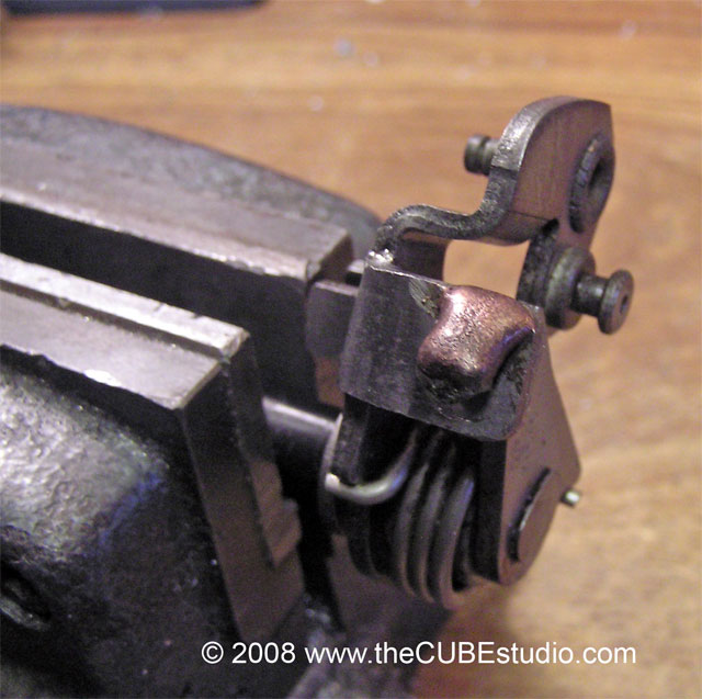
From the factory, the balance
screw is welded/brazed as a means of preventing tampering. There may or may not
be a ‘collar’ around the balance screw.
http://www.thecubestudio.com/pictures/CF_TBrefurb/LinkageWeldWEB.jpg
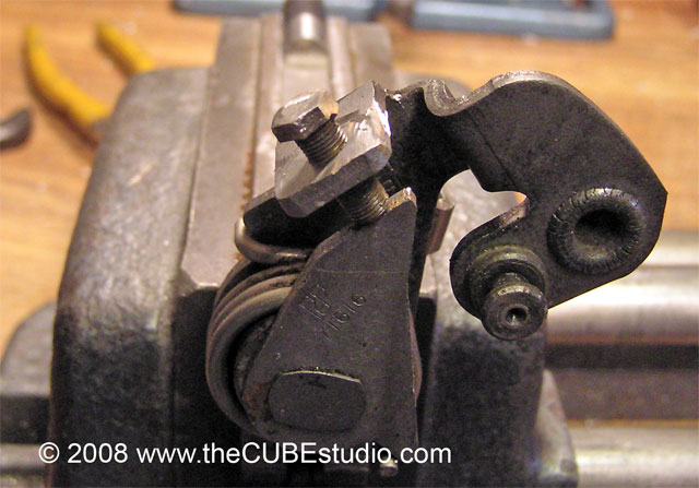
You will need to remove this
weld in order to balance the TBs. Now is the time. An abrasive cut off wheel
makes short work of the weld. A hacksaw can also do the job. In any event, once
you have the weld removed, if there is a collar on the screw, you can just turn the collar to balance, or you can
take the screw all the way out, remove the collar and put the screw back in. If
you do that, be aware that the screw will not be sitting where it needs to be
and you will have to fiddle around with the linkage arms to get it back where
it belongs. In the end, you want something like this:
http://www.thecubestudio.com/pictures/CF_TBrefurb/LinkageWeldBrokenWEB.jpg
Take note of how the screw
bears upon the arm below. The part that the screw threads thru and the part
that it pushes against are two different arms. Turning the screw changes
the relationship between the front and rear TB throttle shafts . . that’s how
it is balanced. Do not even think
about trying to get a new screw.
It is a very, very fine
pitch for its size and you will not find one. If the screw gets jazzed
up somehow, figure on re-tapping for a different screw.
Removing the anti tamper
caps covering the idle stop screws has been described to me as one of the
‘scary’ parts of TB rebuilding because you have to drill into the throttle
body. Well, it is very easy to do and you don’t need to worry about ‘ruining’
the TB. There are no fuel or air passages anywhere near where you will be
drilling. The very worst you will do is make a sloppy hole or one that’s bigger
then you needed, and you have the TBs off the car, so you can drill from the
bottom so no-one will ever see it.
Since drilling into the
TB has been described to me as a
scary affair, I am going to spend some time and provide lots of pictures on
this step.
If you have ‘anti tamper’
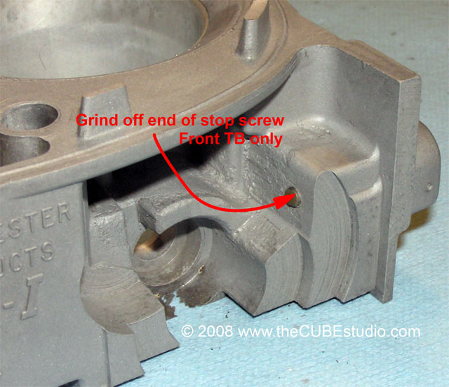
caps covering the idle stop adjustments, you will need to remove at least the
one on the rear TB. The front TB also has an idle stop screw but it is not used
and in fact should not be touching the linkage once everything is back
together. To guarantee that, you can punch out the anti-tamper cap and remove
the screw all together. You may need it anyway to replace a jazzed up screw on
the Rear TB. You can also leave the front TB cap in place (it looks nicer that
way) and lightly grind off the tip of the screw protruding from the casting.
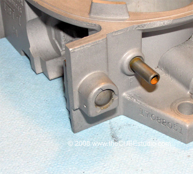
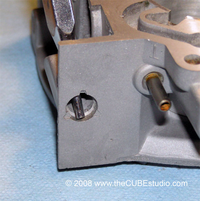
This is what the Anti Tamper
Caps look like from the factory . . note the three stakes are all that hold it
in:
http://www.thecubestudio.com/pictures/CF_TBrefurb/ATcapUnmolestedWEB.jpg
You can choose to leave the
cap in the front TB and just grind off the protruding tip to be sure it does
not interfere with balancing later:
http://www.thecubestudio.com/pictures/CF_TBrefurb/ATcapGrindScrewTipWEB.jpg
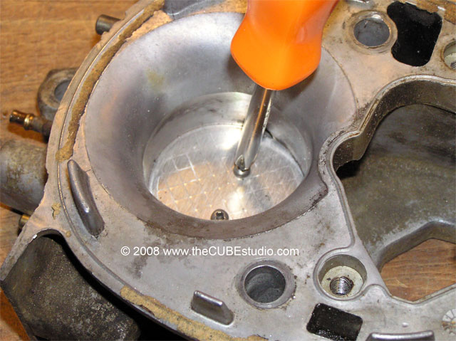
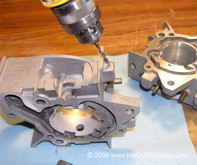
To get the anti tamper caps
out, turn the TB upside down on your bench and drill a small hole down
diagonally that ends at the back of the cap. Start the drill about ¼” back from the cap. Don’t go back
farther because there is still a stop screw in there and we want to miss the
head of that screw so we need to stay pretty close to the end. If you do nick
the head of the screw, it’s no big deal. The screw head is soft and it will
still work fine with a little bite out of it.
http://www.thecubestudio.com/pictures/CF_TBrefurb/ATcapDrillStartRearWEB.jpg
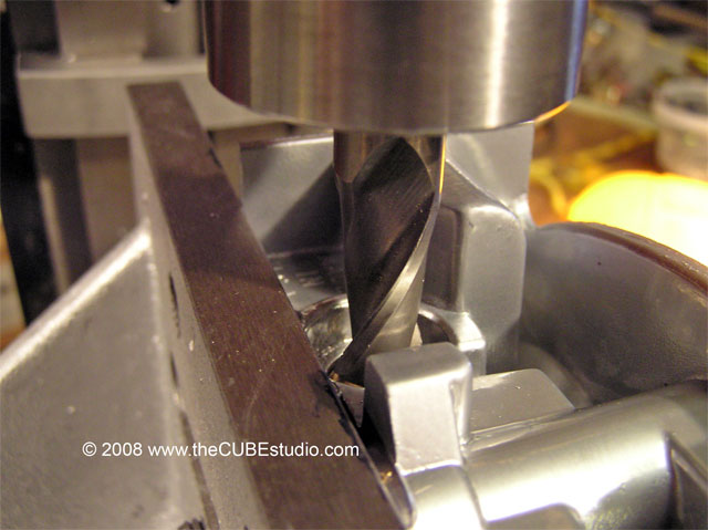
Drill straight down until
the drill bit has gone a tiny bit into the soft metal. Then while continuing to
drill, angle the drill backward so that the drill bit is heading diagonally
down and toward the back of the cap.
http://www.thecubestudio.com/pictures/CF_TBrefurb/ATcapDrillEndRearWEB.jpg
Make the hole slightly
larger than your smallest pin punch. If you do not have a pin punch, you can
use a jeweler’s Philips screwdriver or even a 12 penny nail to punch out the
cap once you have the hole drilled.
Put the punch tool into the
hole and tap the cap right out.
Don’t bother trying to drill thru the cap. It is hardened.
http://www.thecubestudio.com/pictures/CF_TBrefurb/ATcapPunchInPlaceWEB.jpg
The cap will pop right out
and you can see here where the punch was positioned to be effective:
http://www.thecubestudio.com/pictures/CF_TBrefurb/ATcapPunchThruWEB.jpg
This is what you will see
from the top after you are all done. No matter how nasty the hole looks, only
you will know.
http://www.thecubestudio.com/pictures/CF_TBrefurb/ATcapNoHoleOnTopWEB.jpg
If you choose to or need to
remove the cap form the front TB, you won’t be able to go in from the bottom,
but you can go from the side. Start like this:
http://www.thecubestudio.com/pictures/CF_TBrefurb/ATcapDrillStartFrontWEB.jpg
End like this:
http://www.thecubestudio.com/pictures/CF_TBrefurb/ATcapDrillEndFrontWEB.jpg
The original stop screw has a Torx® head. If you just removed
the anti-tamper plug, then likely the head is in good shape and you just need
this short arm Torx® key to turn it.
http://www1.mscdirect.com/CGI/NNSRIT?PMAKA=75472209
If the anti-tamper cap had
been taking out sometime in the past, likely as not someone has tried to use a Phillips
head screw driver to turn the screw and totally jazzed up the head.
In that case, you have two
options. Use the screw from the front TB (it is not needed or used), or go to
you local hardware store and get a 4mm x 25mm cap screw . . stainless is nice.
Get the 3mm key to go with it and ditch the jazzed up original screw.
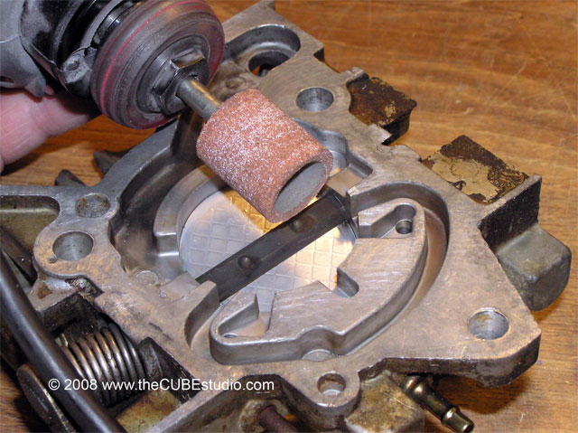
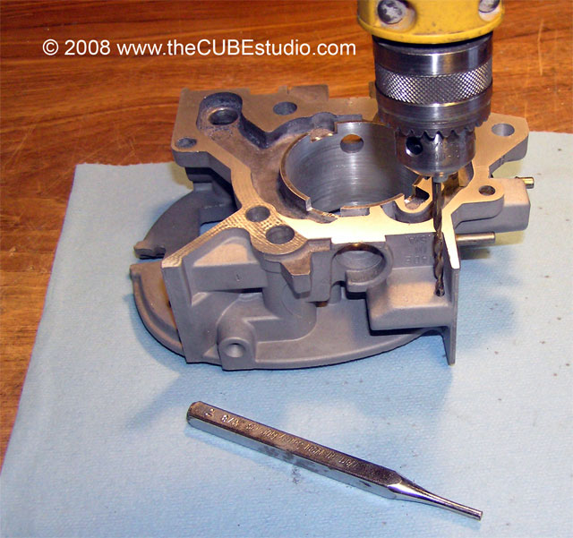
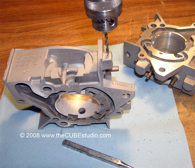
Time to make shavings. The
photo shows a milling machine with a ½” end mill making the cut to receive the
bushing. If you have such an animal, or a friend or brother-in-law who has one,
just make the cut concentric to the shaft hole and 3/8” deep.
http://www.thecubestudio.com/pictures/CF_TBrefurb/BushingMachinePocketWEB.jpg
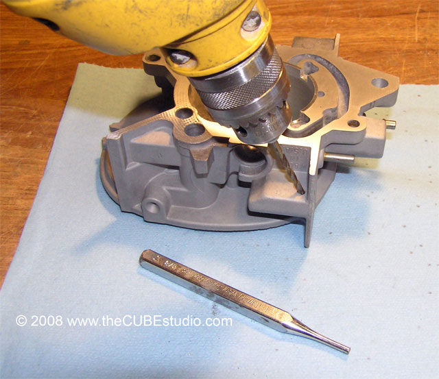
Everyone else get out your
new tools.
Put the pilot in the
cutter! That will guarantee that you
make a straight concentric cut. Mark the 3/8” depth on the cutter with a permanent
marker (Sharpie) and then at a relatively slow speed, run the cutter in. You
can cut with no oil and the material is VERY soft and cuts very easily. Use a
light touch. Take your time and stay lined up.
Do NOT cut all the way thru
the shaft hole into the throat of the Throttle body. You must make a separate
cut for each bushing, 3/8” deep on each side, starting from the outside of the
throttle body.
Push
the new bushings into the new holes you just made. They should be snug. If they
are tight, do not hammer on the bushing itself. Use any 3/8” bolt that is long
enough to span the TB and slip the bushing onto the bolt. Then slip the bolt
into the throttle body where the shaft would be and tap on the head of the bolt
to seat the bushing. IN this method, the bushing will be forced to stay aligned
and not get cocked sideways as you tap it into the hole. Presto! DONE.
The
bushing may be loose in the new pocket you cut if 1) the original shaft hole
was badly worn (cutter can wander by that much, 2) your have a shaky hand or
got a little croked, or 3) or if
the particular cutter you have is on
the high side of tolerance. It the bushings are loose in the hole, no
problemo, just put some hardening type Permatex or JB Weld epoxy (available at
auto supply or hardware stores . .
both are gasoline resistant) on the outside of the bushing and slip in back in.
Wait for it to dry before messing with it.
STEP TEN
Note: check your shafts arms for straightness. If they are
bent, then go here before proceeding to the next step:
http://www.thecubestudio.com/CrossfireThrottleBodyStraigteningBentThrottleShaftArms.htm
Check
the shafts at the wear points for sharp burs or ripples that stick up above the
surface. Smooth them with 400 grit paper being careful to remove as little
metal as possible. Slide the shafts back in, remembering to get the return
springs on the correct shafts. A trick to getting the return spring seated is
to hook the end around the arm and then stretch the spring slightly to get the
‘lever’ end of the spring into its slot. While holding that lever end in its
slot, rotate the shaft until it is in the correct position and then slide it
the rest of the way in. That may make no sense reading it, but with the parts
in front of you, it should be clear.
STEP ELEVEN
Put
the springs, and other stuff back on the end of the shafts. The spring (front
TB) with the couple of smaller coils can just be forced over the end of the
shaft with your fingernails.
STEP TWELVE
OK
time to pay attention. The throttle blades need to have a good fit in the
throat. Otherwise you will not get a good idle or off-idle behavior. Often they
have their own idea about where they want to end up. Get the throttle plate in
position and put the two screws in loosely. Now open and close the throttle several times. The throttle
plate should seek its own center . . . but it might not. With the throttle closed, hold it up
to a light and look thru the throat. The gap around the blade should be tiny
and as consistent as possible. Snug the screws slightly and re-check. Sometimes
tightening the screws will move the plate and you need to start over. Take your
time and get this part right.
Once you get them tightened,
you’re done! Use thread lock on the screws. I like to put a tiny drop of green
loctite on the end of the screws after they are tight. Green is designed to
‘wick’ into tiny cracks. It is somewhere between blue and red in holding power.
It is thin, so don’t squeeze the tube much you you’ll have a mess.
Congratulations, you just
saved 30 or 40 bucks, a couple weeks of down time and you know your TBs are
done right.
This document covers the simplest
method of installing shaft bushings. There are two other methods of installing
bushings/bearings on the shafts.
1) Undersized bushings that are reamed in place to get
perfect clearance and alignment.
(better)
2) Sealed stainless steel ball bearings. (best)
These methods, as well as
how to properly balance the TBs when you are done, will be covered in separate documents.
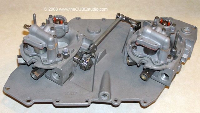
When you get it all back
together, it should look something like this:
http://www.thecubestudio.com/pictures/CF_TBrefurb/PippinFrontWEB.jpg