Subject: Crossfire Throttle Shaft ARM straightening
Initial Release 06/10/08
Revision 01 07/25/08 added links and updated
article descriptions
Revision 02 08/05/08 Add ref to REAMED bushing
article
Straightening
bent shafts and arms.
Difficulty
level: EASY – Special machines required: bench Vice, Locking Pliers (ViseGrip)
Note: IF arms are loose on shafts.
Difficulty level is then: Moderate – Special machines required: Brazing torch.
© 2008 Steve
Simpson – www.theCUBEstudio.com - steve@thecubestudio.com
IMPORTANT
NOTE:
These tech articles go thru periodic revisions to add or update info. The link
does not change, so check back before you use the instructions to be sure you
are using the latest version.
**
I want to add my thanks for the excellent feedback I have gotten. There’s no
point in doing this if I’m not providing the info people want, so the
contributions from readers are all valuable. **
Note:
use the browser back button after viewing links in this document. Adobe
.PDF versions of these articles (that can be printed including the pictures)
will be available soon
This is the fifth in a
series of tech HOW-TO articles on maintaining and improving the crossfire
injection system
Articles released so
far:
Crossfire Throttle Body Rebuild including
Installation of standard Shaft bushings Difficulty Level: EASY – Special machines required:
NONE
http://www.thecubestudio.com/CrossfireThrottleBodyRestoration.htm
A special follow-on
article by request is here:
http://www.thecubestudio.com/CrossfireTechFixingFailedAttemptToRepairBrokenOffScrews.htm
Crossfire
Throttle Body Rebuild including Installation and REAMING of accurate Shaft
bushings Difficulty Level –MEDIUM – Special machines required -
Drill press with vice
http://www.thecubestudio.com/CrossfireThrottleBodyRestorationREAMEDBushings.htm
Straightening bent
shafts and arms. Difficulty level: EASY – Special
machines required: bench Vice.
Above operation IF arms are
loose on shafts. Difficulty level: Moderate – Special machines required:
Brazing torch.
http://www.thecubestudio.com/CrossfireThrottleBodyStraigteningBentThrottleShaftArms.htm
Building your own
water manometer for $6 in materials from any hardware store. Difficulty level: EASY – Special machines required:
NONE
http://www.thecubestudio.com/CrossfireHomeBuiltManometer.htm
Correctly and
accurately balancing the Throttle bodies. Difficulty level: EASY – Special machines required:
Water Manometer, air passage plugs (home made)
Above operation IF balance screw if
still welded. Difficulty level: Moderate – Special machines required: Rotary
cut-off tool or hacksaw
http://www.thecubestudio.com/CrossfireThrottleBodyBalancing.htm
Follow on articles will cover:
Adding sealed stainless
ball bearings to the TB shafts instead of simple bushings. (best)
Difficulty level: Advanced – Special machines required – Lathe
Note: After some thought
and discussion, I have concluded that this is NOT a do-it-yourself project and this article may not be released.
Feel free to comment on that.
Rebuilding the
injector POD. Difficulty level: EASY – Special
Machines required: NONE
This will be the next
article released and the article now contains some optional special performance
modifications which will require
machining. Standard rebuild is still EASY no special tools.
Porting the crossfire
manifold. Difficulty level:
Advanced – Special Machines required: Die Grinder (not a Dremel tool),
Non-ferrous carbide cutters, Sawzall
or rotary cut-off tool,
Milling machine. Metal forming skills.
One additional article
specific to the 1982 Collector Edition Rear Glass Hatch is here:
http://www.thecubestudio.com/CollectorEditionHatchHingeInstallationInstructions.htm..
“Why should I care if
the throttle arms are bent?”
OK, first some background:
All
carburetors and Throttle Bodies originally designed for multi-carb setups have
some mechanism built in to do a balance a.k.a. synchronization.
GM
decided that in order to keep people (including mechanics) from messing with
the factory balance, the adjustment mechanisms would be hidden, or welded. In
the case of Crossfire TBs the idle stop screws are covered by hardened steel
caps (typical) and the balance
adjustment screw is welded to the shaft arm to keep it from being ‘tampered’
with.
The
factory manual instructs to break the weld to make required adjustments.
Unfortunately, most mechanics do not have factory manuals for every car they
work on and the method chosen by some mechanics to make adjustments is to bend
the arms on the throttle shafts. This is not entirely difficult to understand
as some carburetor adjustments are properly made by bending tabs, so that
method is common.
On the
other hand, I have had ‘experienced crossfire specialists’ tell me that bending
the arms is the ‘correct’ factory procedure! The moral of that story is to be
skeptical of what you hear about crossfire injection.
Bending
the arms is certainly NOT the correct procedure and with good reason. Lets look
at some facts:
1) The crossfire
is very sensitive to balance, ridiculously so, actually. You hear a lot about
idle quality, but the crossfire is also especially sensitive to balance just
off idle (the infamous crossfire
stumble) and what is called ‘tip-in’ where you reapply throttle at speed
after backing off for a corner or obstacle.
2) The
rear TB shaft arm operates the front TB shaft arm.
3) In order for
the two shafts to rotate at the same rate, the distance from the center of the
shaft to the center of the connecting link must be the same. Like the wheels of
a steam locomotive.
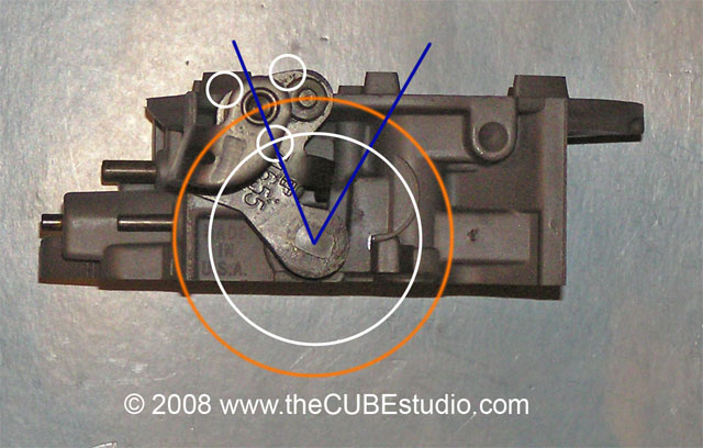
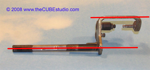
4) The spot
where the link is connected to the rear TB is cantilevered WAY out away from
the TB, and therefore a bend in the arm will drastically change the distance
from the centerline of the shaft to the centerline of the pin that drives the
connecting link. In the next photo the white circles represent possible
positions of the pin with a bent arm. The circles show the path the pins would
take and the blue line show the start and stop points of the pin for the same
amount of shaft rotation. It is obvious that the pin tracing the white circle
would travel less distance then the original orange circle shows.
http://www.thecubestudio.com/pictures/StraightenTBshaft/SideViewWEB.jpg
Therefore
it is not a matter of opinion, expert or otherwise, whether bent arms effect
the system balance. It is a fact based upon simple high school
geometry. If the throttle arm on the rear TB is bent, you can still balance at idle,
but the more the throttle opens, the more out of balance the TBs become. If you
ever expect to get a Crossfire to run right, you MUST have straight shaft arms.
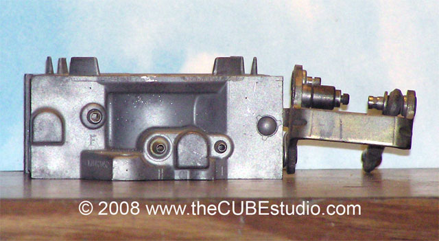
OK, let’s look
at a real world example. The following photo is not staged for the purpose of
having an extreme example for this article. This is pretty typical of what I
see. This is not even particularly bad. I see this not only with original TBs,
but also on freshly ‘rebuilt’ TBs and also on several ‘wide body’ bored out
Crossfire TBs. This is not really
all that surprising considering that straightening bent throttle shaft arms is
not normally part of rebuilding a
carburetor or throttle body, because in most cases, they don’t get bent up, of if
they do, it doesn’t effect the operation.
http://www.thecubestudio.com/pictures/StraightenTBshaft/BENTarm06WEB.jpg
http://www.thecubestudio.com/pictures/StraightenTBshaft/BENTarm05WEB.jpg
Fortunately, this is not difficult to fix. If your TBs have
been ‘rebushed’, ‘rebuilt’ ‘refurbished’ or ‘bored’, it should be simple to get
them apart to straighten the arms. If your TBs are original, then you will need
to stop here and go thru the following article on rebuilding your TBs to get
the shafts out.
http://www.thecubestudio.com/CrossfireThrottleBodyRestoration.htm
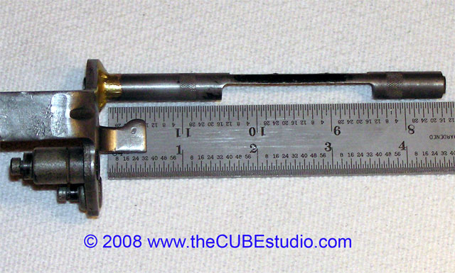
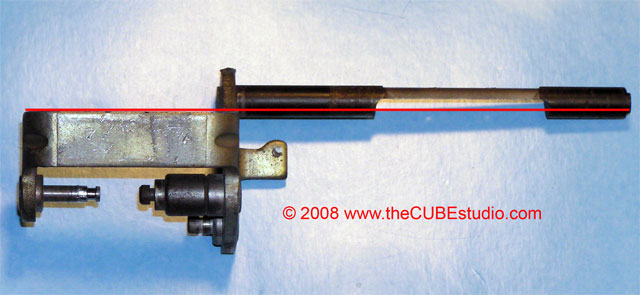
It is
a really bad idea to try to straighten the arms with the shafts in the
TBs. What you will likely do is crack the TB casting or loosen the arm on the
shaft requiring it to be brazed back on like this one. This shaft was on a TB traded
in for an UltraMod TB. The arm was bent up big time and rattling loose on the
shaft. All better now:
http://www.thecubestudio.com/pictures/StraightenTBshaft/ArmBrazedWithRulerWEB.jpg
OK
lets begin with the bent up shafts out of the TB.
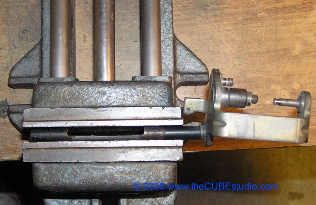
Lets
get a shaft in the vise and see what we have to deal with.
http://www.thecubestudio.com/pictures/StraightenTBshaft/BENTarm04WEB.jpg
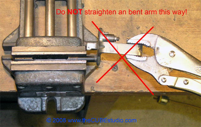
Nasty.
Seemingly, the obvious move is to grab the arm and bend it back like so:
http://www.thecubestudio.com/pictures/StraightenTBshaft/NOTthisWay01WEB.jpg
The
result here would be either bending the shaft itself or loosening the arm on
the shaft. Neither is the objective, so what is important is to bend the arm against the arm itself and never against
the shaft.
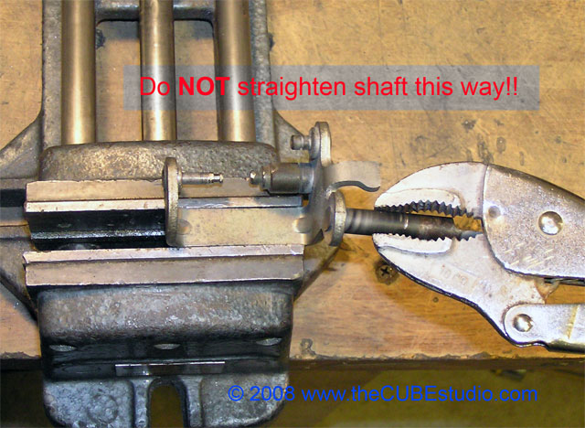
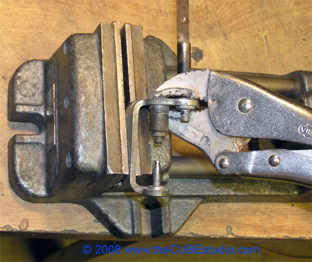
That rule applies in both directions so the following method is also ‘illegal’:
http://www.thecubestudio.com/pictures/StraightenTBshaft/NOTthisWay02WEB.jpg
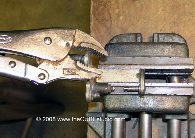
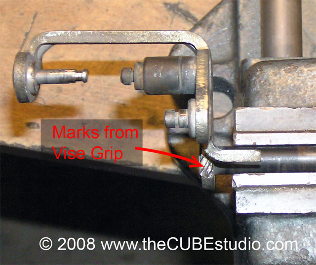
Some
may not like this step as it WILL leave deep marks in the arm, but in my
opinion, this is preferable to bending the shaft or needing to get out the
torch.
Arrange
the arm in the vise like this and grab the ARM itself at the shaft with your
locking pliers and bend from there:
http://www.thecubestudio.com/pictures/StraightenTBshaft/DOthisWay03WEB.jpg
This
method protects the shaft from damage and results in a nice straight arm (in
one plane). Note that from most angles, the jaw marks are not visible. Besides,
since the crossfire TBs reside under an air cleaner that could easily double as
a sun shade for the average playground, the TBs can be ugly.
http://www.thecubestudio.com/pictures/StraightenTBshaft/MarksFromViseGripWEB.jpg
http://www.thecubestudio.com/pictures/StraightenTBshaft/ArmStraightInViseWEB.jpg
Focus
on one plane at a time. In this step we are concerned with the straightness
looking from the top down, and we want this result:
http://www.thecubestudio.com/pictures/StraightenTBshaft/ArmStraightTopWEB.jpg
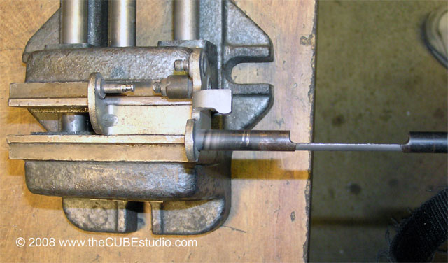
Now address
the other plane looking from front to back and straighten that direction, again making sure to bend against the
arm and NOT against the shaft. Here is one way to accomplish that:
http://www.thecubestudio.com/pictures/StraightenTBshaft/DOthisWay01WEB.jpg
And
the result we are looking for:
http://www.thecubestudio.com/pictures/StraightenTBshaft/ArmStraightSideWEB.jpg
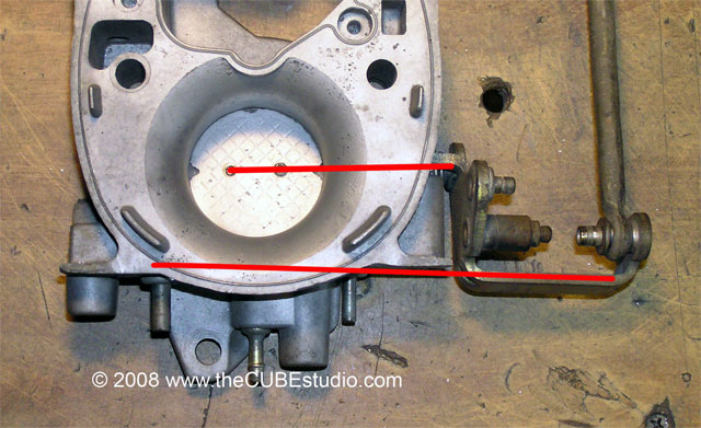
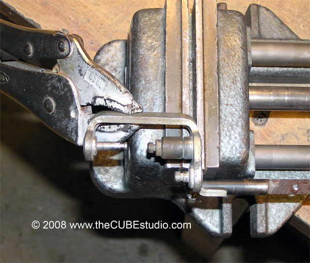
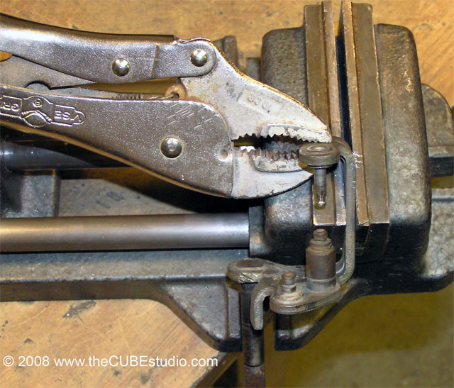
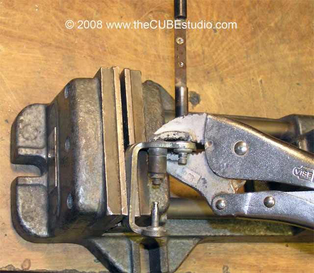
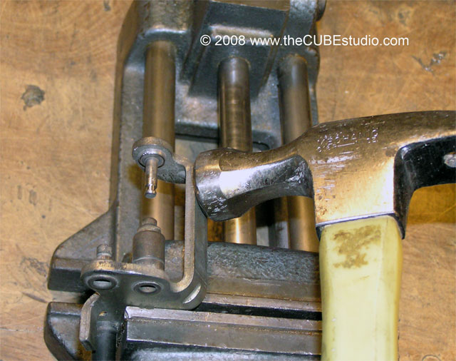
On the crossfire rear TB arm
there are two pins that should directly face each other and line up exactly.
The outboard pin is the important one that drives the connecting link to the
front TB. We want to get that pin into the proper position, The easy way to do
that is to have it pointing at and aligned with the opposing pin.
Study
the following photos and note that the rule of never bending against the shaft
is followed in each setup.
http://www.thecubestudio.com/pictures/StraightenTBshaft/DOthisWay02WEB.jpg
http://www.thecubestudio.com/pictures/StraightenTBshaft/DOthisWay05WEB.jpg
http://www.thecubestudio.com/pictures/StraightenTBshaft/DOthisWay04WEB.jpg
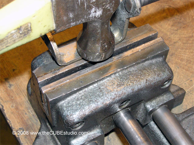
This is an optional step
only for those like myself who are insufferably anal. If you have the pins
lined up, you’re good to go, but if your Karma can’t handle having the top of
the arm looking like an old sway back mule, you will need to get the arc out of
the flat part. This is easily done by tapping with a hammer against and anvil .
. or in my case the stationary
side of a vice. I abuse tools on a regular basis, and break quite a few in the
process, but even I don’t hammer on the open moveable side of a vise.
Also keep in mind that we
are not forging medieval weapons here. It’s soft steel and only needs a little
coaxing . tap tap tap, that’s it.
http://www.thecubestudio.com/pictures/StraightenTBshaft/Hammer02WEB.jpg
http://www.thecubestudio.com/pictures/StraightenTBshaft/Hammer01WEB.jpg
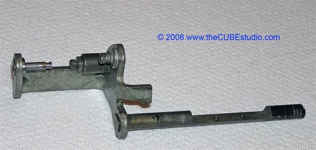
Here
is the finished cleaned up shaft ready to be fit to new bushings or knurled for
ball bearings (separate articles).
http://www.thecubestudio.com/pictures/StraightenTBshaft/ArmFinalCleanWEB.jpg
Instructions
for straightening the shaft itself are contained I the TB rebuild article.